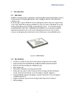
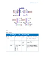
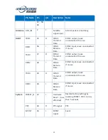
background image


UM4B0 

GPS/BDS/GLONASS/Galileo Four-
System Undeca-Frequency High 
Precision RTK Module 

Summary of Contents for UM4B0

Page 1: ...UM4B0 GPS BDS GLONASS Galileo Four System Undeca Frequency High Precision RTK Module...

Page 2: ...represent a commitment on the part of Unicore Communications Inc No part of this manual may be reproduced or transmitted in any form or by any means electronic or mechanical including photocopying an...

Page 3: ...nicore UM4B0 product For the generic version of this manual please refer to different part of the manual according to your purchased product configuration concerning CORS RTK and Heading Readers it ap...

Page 4: ...0 REFERENCE DESIGN 10 3 3 PINS 11 3 4 PCB PACKAGING 13 3 5 RESET SIGNAL 13 3 6 ANTENNA 13 4 INSTALLATION AND CONFIGURATION 14 4 1 ESD HANDLING PRECAUTIONS 14 4 2 HARDWARE INSTALLATION 15 4 3 START UP...

Page 5: ...cation experience even in the most challenging environments such as urban canyons by deploying anti interference function block and on board MEMS device Figure 1 1 UM4B0 Module 1 2 Key Features 30 40m...

Page 6: ...to First Fix TTFF Cold start 25s Vertical 3 0m Reacquisition 1s DGPS RMS Horizontal 0 4m Correction RTCM 2 3 3 0 3 2 Vertical 0 8m RTK RMS Horizontal 10mm 1ppm Data Output NMEA 0183 Unicore Binary Ver...

Page 7: ...C4C0 2 Nebulas II SoC UC4C0 Nebulas II UC4C0 is Unicore s new generation high precision GNSS SoC with 55nm low power design supports up to 12 digital intermediate frequency or 8 analog intermediate fr...

Page 8: ...4 2 Hardware 2 1 Dimensions Table 2 1 Dimensions Symbol Value mm Tolerance mm A 40 00 0 2 0 5 B 30 00 0 2 C 4 00 0 2 D 1 58 0 1 E 1 27 0 1 PIN 1 07 Figure 2 1Mechanical Dimensions...

Page 9: ...cription 1 GND Ground 2 ANT_IN I GNSS antenna signal input 3 GND Ground 4 GND Ground 5 ANT_PWR I GNSS antenna power supply 6 GND Ground 7 ANT_NLOD O GNSS antenna open circuit indicator 1 normal 0 ante...

Page 10: ...default clear all user settings LVTTL active low press longer than 5 seconds 23 ERR_STAT O Abnormal indicator active high When the RTK solution is fixed it outputs high level alternatively outputs lo...

Page 11: ...7 GND Ground 48 RSV RSV 49 RSV RSV 50 RSV RSV 51 RSV RSV 52 GND Ground 53 RSV RSV 54 RSV RSV 55 GND Ground 56 RSV I RSV 57 GND Ground 58 GND Ground 59 RSV I RSV 60 GND Ground 2 3 Electrical Specificat...

Page 12: ...Antenna Gain Gant 20 30 36 dB Noise Figure Nftot 2 5 3 3 5 dB LNA Input ANT_PWR 3 3 5 5 5 V 100mA Operating Temperature Topr 40 85 C Power Consumption P 1 5 1 8 2 0 W NOTE Because of the capacitance i...

Page 13: ...ecessary for firmware upgrades Properly connect the module s reset pin FRESET_N to ensure reliable reset of the module It will restore to manufactory configuration When ANT_NLOD ANT_FFLG and antenna d...

Page 14: ...circuit is short and smooth try to avoid acute angle Try to avoid circuits below UM4B0 This module is a temperature sensitive device dramatic changes in temperature will result in reduced performance...

Page 15: ...wer Supply VCC 31 32 Power Voltage Supply Stable clear low ripple power supply peak ripple power lower than 50mVpp is preferred ANT_PWR 5 Power Antenna Power Supply Voltage supply for active antenna G...

Page 16: ...e TXD2 37 O COM2 Transmit Data COM2 output leave unconnected if no use RXD2 38 I COM2 Receive Data COM2 input leave unconnected if no use TXD3 39 O COM3 Transmit Data COM3 output leave unconnected if...

Page 17: ...re effective reset the reset pin RST and power supply pin VCC must meet the following time sequence To reset UM4B0 during normal operation please pull RST pin to low level for more than 5ms VCC RST 5m...

Page 18: ...s to the device All operations mentioned in this chapter shall be carried out in an antistatic workbench using both wearing an antistatic wrist strap and a conductive foam pad If antistatic workbench...

Page 19: ...steps below to install Step 1 Make sure to make full anti static measures such as anti static wrist strap grounding the workbench Step 2 Align UM4B0 transfer board positioning holes and pins with EVK...

Page 20: ...GNSS antenna with appropriate gain fix it in the stable non block area using the coaxial radio frequency cable to connect the antenna with UM4B0 EVK Step 4 Connect the PC to the EVK serial port throug...

Page 21: ...ting tools are available for module testing 4 4 Configuration and Output Unicore UPrecise software provides a user friendly graphical interface to control and display the operation of your receiver Th...

Page 22: ...r the tracking window Switching between Constellation Views Resetting the Receiver Replaying the GGA log Figure 4 5 UPrecise Software 4 4 1 Operation Procedures Step 1 Follow 4 2 Installation Guide to...

Page 23: ...ear log content etc Step 6 View and use various views of UPrecise and configure or input commands as required 5 Configuration Commands UM4B0 supports abbreviated ASCII format No parity bit simple ASCI...

Page 24: ...less than 2 5 meter height accuracy is achieved When restart after power off the calculations will repeat and a new datum point coordinates generates bestpos Get datum point coordinates lat lon height...

Page 25: ...ed Message type could be set by oneself Heading information includes HDT heading TRA 5 1 RTK Reference Station Configuration If the precise coordination is known the precise coordinate could be set as...

Page 26: ...will receive the satellite information and sent to the mobile station receiver to be determined directly or after processing Moving base station receiver receives satellite observations at the same ti...

Page 27: ...not fed by ANT_PWR but by other means the query result is invalid 7 Inertial Navigation UM4B0 has built in inertial navigation devices please follow the instructions in the Reference Commands Manual f...

Page 28: ...ecise software is used for the remote update of UM4B0 please follow the steps below to upgrade the device Figure 8 1 Update Interface Click to browse the firmware update package and click Start to sta...

Page 29: ...UM4B0 User Manual 25 Figure 8 2 Update Steps Waiting for the process to complete 100 the upgrade time is normally within 5min Figure 8 3 Update Steps Please use COM1 only to update firmware...

Page 30: ...eheating temperature range 150 180 Reflux Stage Over melting temperature 217 time 40 60 s Peak temperature for welding no higher than 245 Cooling Stage Cooling Slope Max 4 s Notes In order to prevent...

Page 31: ...s are relatively low if using this welding method please give priority to other components on the Board 10 Packaging UM4B0 modules are delivered in trays which is suitable for mainstream SMT equipment...

Page 32: ...www unicorecomm com Unicore Communications Inc www unicorecomm com Phone 86 10 69939800 Fax 86 10 69939888 info unicorecomm com 7 F3 No 7 Fengxian East Road Haidian Beijing P R China 100094...

Reviews: