background image


Documentazione Tecnica 

CIB Unigas - Campodarsego (PD)

Complying with

90 / 396 / CEE

GAS DIRECTIVE

MANUAL OF
- INSTALLATION
- OPERATION
- MAINTENANCE

DUAL FUEL BURNERS
L.P.G. - LIGHT OIL

HS5
HS10
HS18

M039131AA Rev. 0 07/04

Summary of Contents for HS10

Page 1: ...ocumentazione Tecnica CIB Unigas Campodarsego PD Complying with 90 396 CEE GAS DIRECTIVE MANUAL OF INSTALLATION OPERATION MAINTENANCE DUAL FUEL BURNERS L P G LIGHT OIL HS5 HS10 HS18 M039131AA Rev 0 07 04 ...

Page 2: ...ssory equipment only shall be used z This unit shall be employed exclusively for the use for which it is meant Any other use shall be considered as improper and therefore dangerous The manufacturer shall not be held liable by agreement or otherwise for damages resulting from improper installation use and failure to comply with the instructions supplied by the manufacturer 2 SPECIAL INSTRUCTIONS FO...

Page 3: ...animals or damage to property for which the manufacturer cannot be held liable z Before installation it is recommended that all the fuel sup ply system pipes be carefully cleaned inside to remove foreign matter that might impair the burner operation z Before the burner is commissioned qualified personnel should inspect the following a the fuel supply system for proper sealing b the fuel flow rate ...

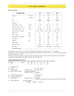
Page 4: ...age 4 BLAST TUBE LENGHT see overall dimensions Available versions S Standard L Long 5 DESTINATION COUNTRY see data plate 6 SPECIAL VERSIONS A Standard 7 EQUIPMENT Available versions 0 2 Valves 1 2 Valves leak detection monitor on request if output 1200 kW 8 GAS TRAIN SIZE see specifications 15 Rp1 2 20 Rp3 4 25 Rp1 BURNER MODEL HS5 HS10 HS18 Output min kW 35 65 80 max kW 70 140 200 Fuel L P G Ligh...

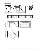
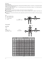
Page 5: ...134 M8 HS18 350 175 265 525 615 430 255 125 210 135 105 134 M8 BACK PRESSURE IN CONBUSTION CHAMBER mbar HS5 kW HS10 kW Fig 2a Fig 2b BACK PRESSURE IN CONBUSTION CHAMBER mbar HS18 kW Fig 3a Dima di foratura piastra caldaia 0 0 5 1 1 5 2 2 5 28 32 36 40 44 48 52 56 60 64 68 72 76 0 0 5 1 1 5 2 2 5 3 3 5 4 50 60 70 80 90 100 110 120 130 0 1 2 3 4 5 60 80 100 120 140 160 180 200 220 ...

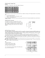
Page 6: ...ation and whose dimensions are described in the diagram in Fig 5 In case the burner must be coupled with boilers with a combustion chamber smaller in diameter or shorter than those described in the diagram please contact the supplier to verify that a correct matching is possible with respect of the application involved To correctly match the burner to the boiler verify the necessary input and the ...

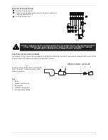
Page 7: ... group 5 Leakage control device z Remove the burner cover z Carry out the electrical connections to the power supply con nector as shown in Fig 6 z Refit the burner cover Fig 6 RESPECT THE BASIC SAFETY RULES MAKE SURE OF THE CONNECTION TO THE EARTHING SYSTEM DO NOT REVERSE THE PHASE AND NEUTRAL CONNECTIONS FIT A DIFFERENTIAL THERMAL MAGNET SWITCH ADEQUATE FOR CONNECTION TO THE MAINS Fig 7 Burners ...

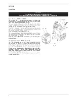
Page 8: ...sure stabilizer is adjusted by operating the screw VS loca ted under the cover C By screwing down the pressure is increased and by unscrewing it is reduced Note the screw VSB must be removed only in case of replace mente of the coil Leakage control device VPS504 Optional The VPS504 check the operation of the seal of the gas shut off val ves costituting the MB DLE This check carried out as soon as ...

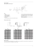
Page 9: ...imer must be installed to delay the valve opening The direct connection of the device without a timer may cause pump breaks Sizing the light oil pipeline Fig 10 Tab 1 Tab 2 Tab 3 H m L m H m L m H m L m Ø 6 Ø 8 Ø 10 Ø 6 Ø 8 Ø 10 Ø 12 Ø 6 Ø 8 Ø 10 Ø 12 0 41 100 100 0 19 77 100 100 0 18 73 100 100 0 5 70 100 100 1 24 90 100 100 0 5 15 66 100 100 1 100 100 100 2 30 100 100 100 1 13 59 100 100 1 5 100...

Page 10: ...4 15 16 17 18 0 40 1 36 1 44 1 52 1 59 1 66 1 73 1 80 1 86 1 92 1 98 2 04 0 50 1 70 1 80 1 90 1 99 2 08 2 17 2 25 2 33 2 40 2 48 2 55 0 60 2 04 2 16 2 28 2 39 2 50 2 60 2 70 2 79 2 88 2 97 3 06 0 65 2 21 2 34 2 47 2 59 2 70 2 82 2 92 3 02 3 12 3 22 3 31 0 75 2 55 2 70 2 85 2 99 3 12 3 25 3 37 3 49 3 60 3 71 3 82 0 85 2 89 3 06 3 23 3 39 3 54 3 68 3 82 3 95 4 08 4 21 4 33 1 00 3 40 3 60 3 80 3 98 4...

Page 11: ... pressure 2 bar max Return pressure 2 bar max Suction height max 0 35 bar to avoid air separation from oil Rated speed 3600 rpm Pump Suntec AS47 A Viscosity 2 12 mm s cSt Fuel temperature 0 60 C into the pump Inlet pressure 2 bar max Return pressure 2 bar max Suction height 0 45 bar max to avoid air separation from oil Rated speed 3600 rpm max Fig 14 Pumps Delta VM Viscosity 2 50 cSt Oil temperatu...

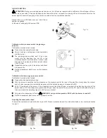
Page 12: ...lue is reduced to 80 ppm then screw down the adjusting ring nut until the burner lockout z Fully open the manual shut off valve WARNING carry out this operation ONLY with the burner turned off z Refit the transparent plastic cover on the pressure switch Adjusting the combustion head To adjust the combustion head rotate the ring nut VR Rotate clockwise toclose the combustion head or turn counterclo...

Page 13: ...D RAPIDITY OF OPERATION ALSO FUNCTIONS AS AN EMERGENCY SWITCH AND ON THE RESET BUTTON IN THE EVENT OF REPEATED LOCKOUTS DO NOT PERSIST WITH THE RESET BUTTON AND CONTACT QUALIFIED PERSONNEL WHO WILL PROCEED TO ELIMINATE THE MALFUNCTION WARNING DURING NORMAL OPERATION THE PARTS OF THE BURNER NEAREST TO THE GENERATOR COUPLING FLANGE CAN BECOME VERY HOT AVOID TOUCHING THEM SO AS NOT TO GET BURNT OPERA...

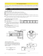
Page 14: ...ollowing the diagram in Fig 20 WARNING All operations on the burner must be carried out with the mains disconnected Correct position of electrodes and combustion head Fig 19a e Fig 19b z Prepare a stable surface where lean the burner during maintenance z To gain access to the combustion head and to the nozzles slacken the screw on the blast tube and remove it from the part that remains fixed to th...

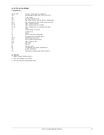
Page 15: ...d valve 1st stage EVG2 Light oil solenoid valve 2nd stage soft start F Fuse FC Flame detetion UV probe IL Mains switch L Phase LB Burner lock out signalling lamp LF Burner operation signalling lamp LGB LANDIS flame controller MA Power supply terminal board MP Light oil pump motor MV Fan motor N Neutral R1 Auxiliary relay ST Thermostats or pressure switches serie TA Ignition transformer TS Safety t...

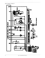
Page 16: ...PART III MAINTENANCE MANUAL 16 Electrical diagram 01 348 Rev 2 ...

Page 17: ...PART III MAINTENANCE MANUAL 17 Electrical diagram 01 352 Rev 1 ...

Page 18: ...NITION ELECTRODE 2080245 FILTER 2090001 FLANGE FOR MULTIBLOC 2191518 BURNER SLIDING FLANGE 2100025 FLEXIBLE HOSE 2340001 PHOTOCELL 2510001 COMPLETE PUMP COUPLING 2540016 MULTIBLOC VALVES GROUP 2190339 GASKET 2110027 TRANFORMATION KIT FOR SHORT TO LONG BLAST TUBE 3091147 TRANFORMATION KIT FOR LONG TO SHORT BLAST TUBE 3091227 PUMP MOTOR 2180004 FAN MOTOR 2180013 PUMP DANFOSS BFP21R3R 2590309 PUMP DE...

Page 19: ...ional 2191604 IGNITION ELECTRODE 2080246 FILTER 2090001 FLANGE FOR MULTIBLOC 2190366 FLEXIBLE HOSE 2340001 PHOTOCELL 2510001 COMPLETE PUMP COUPLING 2540016 MULTIBLOC VALVES GROUP 2190340 GASKET 2110031 TRANFORMATION KIT FOR SHORT TO LONG BLAST TUBE 3091148 TRANFORMATION KIT FOR LONG TO SHORT BLAST TUBE 3091228 PUMP MOTOR 2180004 FAN MOTOR 2180703 FAN MOTOR alternate 2180005 PUMP DANFOSS BFP21R3R 2...

Page 20: ...04 IGNITION ELECTRODE 2080246 FILTER 2090016 FLANGE FOR MULTIBLOC 2190367 FLEXIBLE HOSE 2340001 PHOTOCELL 2510001 COMPLETE PUMP COUPLING 2540016 MULTIBLOC VALVES GROUP 2190341 GASKET 2110031 TRANFORMATION KIT FOR SHORT TO LONG BLAST TUBE 3091149 TRANFORMATION KIT FOR LONG TO SHORT BLAST TUBE 3091229 PUMP MOTOR 2180004 FAN MOTOR 2180703 FAN MOTOR alternate 2180005 PUMP SUNTEC AT245A 2590152 AIR PRE...

Page 21: ... CONTROLLER 22 GAS MULTIBLOC REGULATOR DUNGS MB DLE 405 407 410 412 415 420 25 VALVE PROVING SYSTEM DUNGS VPS504 25 SUNTEC AT2 PUMP 26 SUNTEC PUMPS AS 47 57 67 27 DELTA VM PUMPS 28 NOTES FOR USE AND MAINTENANCE OF FUEL PUMPS 29 APPENDIX COMPONENTS CHARACTERISTICS ...

Page 22: ...y control thermostat pressure controller R Terminal 12 receives voltage and the programming mechanism starts running On completion of waiting time tw with the LGB21 or after air damper SA has reached the nominal load position on completion of t11 with the LGB22 fan motor M will be started tw Waiting time During the waiting time air pressure monitor LP and flame relay FR are tested for correct cont...

Page 23: ...he front part of the safety appliance is located a plexiglass lunette under which there is the indicator disc of programme s progress In the event of safety stop the programmer stops The disc shows as follows the position of the programme at which the interruption occur red no start up the command ring is open interval tw or t10 on LGB21 tw or t11 on LGB22 air damper open LGB22 safety stop block t...

Page 24: ...ductor R Thermostat or pressostat W Safety thermostat or pressostat Z Ignition transformer Key programmer s diagram A start up command from regulator R B burner operation C program start position start up tw waiting time t1 preventilation time TSA safety time t3 pre ignition time t4 interval of time BV1 BV2 or BV1 LR t10 waiting time for confirmation of air pressure t11 air damper movement time to...

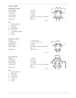
Page 25: ...of valve V2 pressure switch A2 mountable on adapter laterally Closed position signal contact Closed position signal contact type K01 1 DIN tested mountable on V2 Voltage frequency AC 50 60Hz 230 V 15 10 Preferred voltages 240VAC 110 120VAc 24 28VDC 48VDC Electrical connection Plug connection as per DIN 43 650 IEC 335 IEC 730 VDE 0700 VDE 0722 for valves and pressure switches Rating power consumpti...

Page 26: ...nd the suction line flow is equal to the gear set capacity Bleeding in two pipe operation is automatic it is assured by a bleed flat on the pistons but it may be accelerated by opening a pressure port In one pipe operation the by pass plug must be removed and the return plugged Oil which is not required at the nozzle is returned directly to the gear inlet via the pressure regulating valves and the...

Page 27: ... Connection threads cylindrical according to ISO 228 1 Inlet and return G 1 4 with facilities for conical sealing on revision 5 models Nozzle outlet G 1 8 Pressure gauge ports G 1 8 Vacuum gauge port G 1 8 Valve function Pressure regulation and cut off cut off function only assured for model pressure range Strainer open area 14 cm2 opening size 150 µm Shaft Ø 8 mm according to European standard EN...

Page 28: ...l fil ter be installed All twin pipe models can be used as single pipe systems with the simple removal of a nylon plug and by closing the return pipe Technical data Oil viscosity 2 50 cSt 1 1 6 5 E Oil temperature 60 C 140 F max Suction line vacuum 0 5 bar 15 inHg max Suction line pressure 0 7 bar 10 psi max Return line pressure 1 5 bar 21 psi max Cut Off pressure 4 bar Rotation speed 3500 RPM max...

Page 29: ... axis or laterally to avoid excessive wear on the joint noise and overloading the gears z Pipes should not contain air pockets Rapid attachment joint should therefore be avoided and threaded or mechanical seal junctions preferred Junction threads elbow joints and couplings should be sealed with removable sg component The num ber of junctions should be kept to a minimum as they are a possible sourc...

Page 30: ...APPENDIX COMPONENTS CHARACTERISTICS 30 ...

Page 31: ...APPENDIX COMPONENTS CHARACTERISTICS 31 ...

Page 32: ......

Reviews: