background image

15APR2013REV.3.10

DYNAMIC FORCE PROCESSOR

F381A

OPERATION MANUAL

Summary of Contents for DeviceNet F381A

Page 1: ...15APR2013REV 3 10 DYNAMIC FORCE PROCESSOR F381A OPERATION MANUAL ...

Page 2: ...ep this instruction manual so that it can be referred to at any time Safety Precautions In order to have an F381A Digital Indicator used safely notes we would like you to surely follow divide into and and are indicated by the following documents Notes indicated here are the serious contents related to safely Please use F381A after understanding the contents well For safety reasons please read the ...

Page 3: ...tput terminals check the signal names and pin assignment numbers and then carry out wiring properly Be sure to install the attached terminal block cover after wiring to the power input terminals Otherwise electric shocks may result Before applying power carefully check the wiring etc Use at a proper power supply voltage Do not damage the power cord Doing so may cause fire or electric shocks Do not...

Page 4: ...e If the F381Ais not used by the specified method its protective performance may be impaired Maintenance When performing maintenance disconnect the power Do not wipe with a wet rag or with benzine thinner alcohol etc Doing so may cause discoloration or deformation of the F381A In the case of heavy contamination wipe off the contamination with a cloth after dipping it into a diluted neutral deterge...

Page 5: ... by the European Union EU The Directive restricts the use of six specific substances in electric and electronic equipment handled within EU borders The six substances are lead mercury cadmium hexavalent chromium PBB polybrominated biphenyls and PBDE polybrominated diphenyl ethers WARNING Never disassemble deform under pressure or throw the battery into fire The battery may explode catch fire or le...

Page 6: ...ted 14 2 3 External control equipment connection 15 External output equivalent circuits and example connections 15 External input equivalent circuits and example connections 16 Connector pin assignments 17 How to assemble the connector 18 How to check wiring 22 2 4 RS 232C Connection 23 Connector Pin Assignment 23 Communication establishment procedure 23 2 5 Power on 24 3 SCREENS AND OPERATIONS 26...

Page 7: ...MMUNICATIONS 81 5 1 RS 232C 81 Outline 81 RS 232C setting 81 Communication method when the Communication Mode is Normal 83 List of items that can be communicated 83 Set value read command First Setting 87 Set value read command Work Setting 87 Set value write command First Setting 88 Set value write command Work Setting 89 Zero calibration command 90 Actual load calibration command 90 Hold result ...

Page 8: ... 130 Error messages 131 Error Release 132 SD memory card self check 133 8 SPECIFICATIONS 134 8 1 Specifications 134 Sensor input section 134 Display section 135 Setting section 136 Interface 136 Input output section 136 Options 137 General performance 137 8 2 Outside dimensions 138 8 3 Block diagram 139 9 SUPPLEMENTS 140 9 1 Setting tree 140 9 2 Setting item list 142 9 3 Unit setting list 147 9 4 ...

Page 9: ...Contents VIII Contents VIII M E M O ...

Page 10: ...d crystal touch panel display adopted twists have been provided in many places by thoroughly paying attention to ease of understanding so that all operations can be performed without the instruction manual Also having a high speed processing capability of 4 000 times sec ready for fine changes in values and being equipped with the waveform display HI LO limit comparison and other various hold and ...

Page 11: ... limit and method of judgment Each section can be specified by Setting time or displacement or external input signal Hold The method of judgment can be changed by selection under Use Hold Judgment point s can be kept depending on the selection under Use Hold In case of time Time Load In case of displacement Displacement Load In case of time Time Load In case of displacement Displacement Load If a ...

Page 12: ...omparison which should previously be set by time or displacement on a measurement waveform Relative movement can only be made in the Y axis direction Change of the control reference to the point at which loading is started or the point at which it is finished In the case where the X axis of the waveform represents displacement the reference for the hold function and waveform comparison function ca...

Page 13: ...be selected according to application Measurement Start Condition Measurement waveform Displacement Load Comparison waveform Displacement Load In case of Front Displacement Load In case of Back Displacement Load Front Back Measurement Front Back Same back Same front 0mm 0mm Measurement waveform Comparison waveform waveform 5mm 5mm 0mm 5mm 10mm Only External Input External Input Load External Input ...

Page 14: ...splacement Load Displacement Displacement not having Load Time or Stop OFF ON 2048 points advanced for the set time displacement Time or displacement Time or displacement Time or displacement Section Measurement Section Measurement Section Measurement Section Measurement Section Measurement Section Measurement SD card Ethernet RS 232C DeviceNet CC Link Strain gauge type sensor Encoder Load input D...

Page 15: ...he power and internal processing status Lamp condition Power and internal processing status Lights green Power ON Flashes orange Writing in the internal NOV RAM nonvolatile memory or processing with an SD memory card when the SD card slot option is mounted Do not turn off the power of the main unit while this lamp is flashing Flashes yellow The voltage of the lithium battery for internal memory ba...

Page 16: ...ansmit receive measurement data and status information etc The adaptable plug is HOSIDEN manufactured TCP8080 015267 or equivalent Optionally available RS 232C cable cross CA81 232X is connectable Control connector Connector to input external signals and output control signals The input output and internal circuits are photocoupler isolated electrically Input Plus common minus common shared Output...

Page 17: ...eform comparison Hold function Controlling a measurement waveform by dividing it into up to five sections and specifying the method of judgment for each section is called the hold function Judgment point s can be kept depending on the selected method of judgment Use Hold Measurement Acquiring a waveform from the start until it stops is called measurement Waveform reference A reference point is req...

Page 18: ...s 2 Remove the screws two and remove the guide rails from both sides Do not use other screws than those installed to the F381A body 3 Fit in the F381A from the front of the panel 4 Install from the rear the guide rails having been removed from both sides in Step 2 and fix them with the screws two 2 INSTALLATION AND CONNECTION 92mm Panel cut 1 0 Panel thickness 1 6 to 3 2mm dimensions 92mm 1 0 Guid...

Page 19: ...ot to let the tip spread out 5 Tighten the screw with the screwdriver 0 5Nm of tightening torque is recommended 6 Lightly pull the wire to make sure that it is securely clamped 7 Insert the wire connected plug into the F381A body and tighten the screws two How to remove the terminal block 1 Loosen the screws two with a screwdriver 2 Remove the terminal block by giving it a strong pull 5mm Loosen T...

Page 20: ...ut sensor 11 B Terminal to input the B phase output of the pulse output sensor Connect the A phase output of the pulse output sensor 12 Z Terminal to input the Z phase output of the pulse output sensor Connect the A phase output of the pulse output sensor It is not usually wired It is wired only when the indicated value is adjusted to zero at the original point of the rotary encoder Type Pin No Si...

Page 21: ...rtional to the input of the strain gauge type sensor Approx 2V per 1mV V Connect a pen recorder etc for simply monitoring the input of the strain gauge type sensor 7 GND Ground terminal of VOL OUT Displacement input LDI 8 F G Frame ground terminal to connect the shielded wire of the pulse output sensor connecting cable 9 A Terminal to input the A PCA φA output of the pulse output sensor Connect th...

Page 22: ...e can be connected CAUTION The excitation voltage of the F381A is 2 5V 10V If the maximum excitation voltage of the sensor is under 2 5V 10V heating or damage may result EXC EXC SIG SIG F G IN OUT IN OUT F381A body 1 2 3 4 5 EXC EXC SIG SIG F G IN OUT IN OUT F381A body S S 1 2 3 4 5 9 12 10 Vcc F381A Inside Outside COM A DC24V Z A Z COM Open collector output type sensor Ic Approx 10mA 24V 0V NPN t...

Page 23: ...unted It can be connected with Line driver output type sensor Incremental type in accordance with RS 422 like the contact type eddy current type or laser type etc The Line driver input option is order specified 8 9 10 11 12 VIN GND Voltage output Output within 5V F381A body F381A Outside Inside type sensor F G VIN GND Please wire for the power supply of the sensor separately A B Line driver F381A ...

Page 24: ... output equivalent circuits and example connections In case of minus common connection Standard sink type In case of plus common connection ISC source type The plus common connection is order specified Vceo 30V max Output Output COM Ic 30mA max COM Input F381A Sink type PLC etc Plus common connection A13 to A20 B13 to B20 A11 12 B11 12 DC24V Minus common connection 24V 0V Vceo 30V max Output COM O...

Page 25: ...ect the transistor and the photocoupler etc Ic Input Input COM F381A Plus common connection A1 to A8 B1 to B8 A9 10 B9 10 DC24V 24V 0V Push Toggle Switch Switch Relay Approx 5mA Input Input COM F381A Plus common connection A1 to A8 B1 to B8 A9 10 B9 10 DC24V 24V 0V Photocoupler Transistor Ic Approx 5mA Input COM Input F381A Minus common connection A9 10 B9 10 A1 to A8 B1 to B8 DC24V 0V 24V Push To...

Page 26: ...A8 IN Prohibit Touch Panel B8 IN N C A9 IN COM Input Plus common connection 24V Minus common connection 0V B9 IN COM Input Plus common connection 24V Minus common connection 0V A10 IN COM Input Plus common connection 24V Minus common connection 0V B10 IN COM Input Plus common connection 24V Minus common connection 0V A11 OUT COM Output Sink type Standard 0V Source type ISC 24V B11 OUT COM Output S...

Page 27: ...tain digital zero value Please do zero calibration instead DPM Positioning It should be wired according to application Use it for adjusting the zero point of displacement just before measurement start It is not used if the X axis of the waveform represents time or the zero point of displacement does not need to be adjusted By turning the signal from OFF to ON displacement is brought to the DPM Pos...

Page 28: ... OFF to ON during measurement the measurement is forcedly stopped and the measurement data is annulled For keeping the data check the data after completion of the measurement and then turn the Reset signal from OFF to ON Prohibit Touch Panel It should be wired according to application Use it for controlling so as to prevent touch panel operations As long as the signal is ON no operation can be per...

Page 29: ...on is not used Waveform comparison results are output LO Turns ON when the waveform comparison result falls below the LO limit and the output is held HI Turns ON when the waveform comparison result exceeds the HI limit and the output is held OK Turns ON when the Compare Area is passed through during measurement and the LO and HI outputs are not ON after completion of the measurement OK will not tu...

Page 30: ... the instant when the Start input is turned ON and the instant when all outputs but Run are turned OFF Approx 5ms Measurable section OFF ON Start OFF ON Stop OK HI LO Complete Load OK DPM OK OFF ON OFF ON OFF ON OFF ON OFF ON OFF ON t3 t4 t1 1 5ms t2 Wait Off OFF confirmation Select work before the Start input OFF confirmation It enables to confirm the acceptance of measurement start and the state...

Page 31: ...rned ON Approx 50ms However there are differences between measurements t4 Delay time between the instant when the Result output is turned ON and the instant when the Complete output is turned ON Approx 30ms Be sure to check that the output is OFF and then turn OFF the Start input How to check wiring Operation Main screen Setting First Setting System Setting Self Check EXT Check Output Press the ou...

Page 32: ...rst Setting Com Setting Com Mode Insert 6 7 8 5 4 2 1 3 Wire connection surface Side view Metal case Plastic cover Secure with Fit the metal cases into the Din connector and cap with the plastic covers Pin No Signal name 1 DCD 2 RXD 3 TXD 4 DTR 5 GND 6 DSR 7 RTS 8 CTS Case F G hardware For connection with DTE data terminal equipment such as a PC use optionally available RS 232C cross cable CA81 23...

Page 33: ...ts the statement having the same contents as the display reading Check that it can be received properly on the side of the equipment connected If not go back to Step 1 or 2 and check again the cable or communication settings 7 Set again the Communication Mode according to application Operation Main screen Setting First Setting Com Setting Com Mode 2 5 Power on Connect the DC power cord 24V DC 15 2...

Page 34: ...25 2 INSTALLATION AND CONNECTION 25 INSTALLATION AND CONNECTION Chapter 2 M E M O ...

Page 35: ...een configuration 3 SCREENS AND OPERATIONS Main screen Result screen Set value input screen Wave Check screen Display Setting screen Main Main Setting Check Esc OK Display or Esc OK or Each setting Result The previously displayed screen appears The default is Result Single ...

Page 36: ...D OPERATIONS 27 SCREENS AND OPERATIONS Chapter 3 Setting screen Item group screen Each setting item screen Set value input screen Main First Setting Work Setting or Up Up Esc OK or Main Main Each setting Each setting ...

Page 37: ...rt signal input is waited for Input the Start signal Measurement can also be started by pressing the Start key Wait Off It is waited for that the Start signal input is turned OFF Turn OFF the Start signal Wait Lv It is waited for that load or displacement crosses the Measurement Start Level Apply load to the sensor so as to cross the Measurement Start Level Sampling Measurement is in progress The ...

Page 38: ...e Main screen the previously displayed screen appears The default display is Result Single Moves to the Wave Check screen Moves to the Setting screen Simply makes the same movement as the Reset signal Also when the error display appears this key clears it after release Simply makes the same movement as the Start signal This key is valid when the status display is Complete or Wait St When pressed i...

Page 39: ...lt screen Judgment results by the waveform comparison function and hold function last 40 data can be checked A selection can be made from the List display and Single display Result display List Display Result display Displays Nos measurement times overall judgments each section selected by SCT and waveform comparison judgment results No Displays the order of measurement No 01 is the most recent re...

Page 40: ...page number displayed Deletes all comparison results When the Delete key is pressed the deletion confirmation screen appears display selection keys Switch the section displayed Switches the display to Single Moves to the Main screen Result display Single Display Result display Displays the date and time of measurement overall judgment each section and judgment results of waveform comparisons Date ...

Page 41: ... waveform is first exceeded and the Y axis load judgment result No Displays the order of measurement No 01 is the most recent result Wave No Displays the Wave No associated with judgment results It is not displayed if not established Keys Deletes all comparison results When the Delete key is pressed the deletion confirmation screen appears display No selection keys Switch the number displayed Swit...

Page 42: ...ays the HI limit waveform LO limit waveform and area The HI and LO limits correspond to the values of comparison waveforms Switches the display to that for section hold Displays the range HI limit and LO limit of each section The HI and LO limits correspond to those of each section Moves to the Display Setting screen Moves to the Main screen cursor keys Move the cursor rightward leftward area move...

Page 43: ...ns are separated by color for ease of understanding Sections 1 3 and 5 Shaded in gray Sections 2 and 4 Shaded in green Hold judgment point Judgment point s hold point s of each section if any is indicated by a yellow dot However at a Peak to Peak section the minimum value is indicated in pink and the maximum value is indicated in yellow Comparison Comparison Reference Point Waveform comparison Com...

Page 44: ...the present display range 3 You can input numerical values to Y axis Start Point etc but press as it is if such an input is not needed Setting screen Display The present time is displayed Keys Moves to the First Setting screen Moves to the Work Setting screen Moves to the Main screen LO limit of HI limit of HI limit of load LO limit of load displacement displacement Measurement waveform Waveform d...

Page 45: ...lays whether parameters can be changed or not Select by System Setting Keys Moves to the Main screen Moves to the Setting screen Select the work No to make settings The main work No display will not change even if this work No is changed Moves to the set value input screen for Copy Each group Moves to each group screen First Setting Work Setting Parameter protection display Each group Each group ...

Page 46: ...are two or more pages of setting items Order display Displays the setting order Keys Moves to the item group screen Moves to the Main screen Each setting item Moves to the set value input screen Moves to the next page Moves to the previous page Normal display screen Each setting item Setting order display screen Order display Page change Page display Each setting item ...

Page 47: ...tting item screen Move the cursor waveform point according to the setting item Selective item keys Select the item of a set value Selection keys Select the corresponding cursor waveform input item s group s The button of the selected item turns blue Scroll the description of the setting method line by line Numeric keypad input screen 1 Numeric Numeric Numeric keypad input screen 2 Selective input ...

Page 48: ...ain screen Setting First Setting System Setting Work Protect Not Protect Release of First Setting Parameter Protection Operation Main screen Setting First Setting System Setting First Protect Not Protect 4 2 Y axis setting Calibrate and set the load sensor by Y axis Setting Set each item according to the setting order Operation Main screen Setting First Setting Y axis Setting Next Next 4 SETTINGS ...

Page 49: ...Setting Y axis Setting Zero Cal 4 Equivalent Input Calibration Input the rated output and rated capacity display value described on the data sheet of the load sensor Also set the decimal place here Input the decimal point together when inputting the display value Setting range Rated output 9 999 to 9 999 mV V Operation Display value rated capacity 9999 to 9999 Main screen Setting First Setting Y a...

Page 50: ... filter of the set cut off frequency is inserted with respect to the input of the load sensor Operation Setting range 10 30 100 300 Hz Main screen Setting First Setting Y axis Setting Next Next Analog Filter 9 Digital Filter Loads are moving averaged by the set number of times Operation Setting range 0 2 to 999 Times Main screen Setting First Setting Y axis Setting Next Next Digital filter 10 Digi...

Page 51: ...ain screen Setting First Setting X axis Setting Next Next 1 Time Displacement Change Select whether the X axis represents time or displacement Setting range Time Load relative to time is wave formed Displacement Load relative to displacement is wave formed Select Displacement when using a Operation displacement sensor Main screen Setting First Setting X axis Setting Time DPM Change X axis Time X a...

Page 52: ...g Phase Select Only A Phase A Phase of the sensor is used Resolution is 1 pulse Positive counting only A B Phase A B Phase of the sensor is used Resolution is 1 4 pulses The counting conditions are as follows 3 Waveform Reference Select whether the waveform reference is front or back Setting range Front The measurement start point becomes the waveform reference Operation Back The measurement stop ...

Page 53: ... Input the relationship between the number of pulses rated output and displacement value display value determined from the data sheet of the displacement sensor Also set the decimal place here Input the decimal point together when inputting the display value Setting range Rated output number of pulses 1 to 1000000 Operation Display value displacement value 99999 to 99999 Main screen Setting First ...

Page 54: ... together when inputting the calibration value Setting range Calibration value 9999 to 32000 Operation Display value display only Main screen Setting First Setting X axis Setting Next Actual Cal 8 Measurement Length Set the length for waveform acquisition Operation Setting range 2000 4000 6000 8000 10000 Main screen Setting First Setting X axis Setting Next Measure Length 9 Displacement Positionin...

Page 55: ...e work No you want to set Setting range 0 to 15 All When each item is set with the work No specified as All the same set value enters into all of work 0 to 15 on the set item This function is convenient when there is any item you want to set Operation all work in common Main screen Setting Work Setting Work No Work copy Work can be copied Press on the Work Setting screen Set Source and Copy Data t...

Page 56: ...ng Start Condition Only External Input Measurement starts when the external input signal Start turns OFF ON OFF Setting of 2 Measurement Start Level is disabled External Input Load Measurement starts when the load crosses the Measurement Start Level after the external input signal Start turns OFF ON OFF Load Measurement Time or displacement Start OFF ON Section Load Time or displacement Start OFF ...

Page 57: ...acement 9999 to 32000 Main screen Setting Work Setting Start Setting Start Level 3 Measurement Stop Condition Set the Measurement Stop Condition Operation Main screen Setting Work Setting Start Setting Stop Condition Load Displace Start OFF ON Start displacement Measurement Section ment Start level Start point Start point Not crossing Not crossing 〇 Crossing in the negative to 〇 Crossing in the po...

Page 58: ...e load crosses the Measurement Stop Level Time Measurement stops when the forced stop or the time specified under Measurement Stop Level has passed after measurement start Load Time or displacement 2048 points Measurement Section Load Time or Stop OFF ON Measurement Section displacement Load Time or displacement Stop load Measurement Section Stop level Load Stop point Stop point Not crossing Not c...

Page 59: ...ent Stop Condition is Load Time Displacement or Displacement Stop Setting range Load 9999 to 9999 Time 0 1 to 10 0 sec Displacement 9999 to 32000 Operation Displacement Stop 0 1 to 10 0 sec Main screen Setting Work Setting Start Setting Stop Level Load Stop displacement Measurement Section Displace ment Stop level Stop point Stop point Not crossing Not crossing 〇 Crossing in the negative to 〇 Cros...

Page 60: ...pled at 4000sps and the load is kept in a waveform every time the displacement advances Example When the Measurement Length is 4000mm When the displacement returns all the data of the corresponding load is recognized as that of the previous displacement Example When the displacement returns Load Time These data are kept 250μs Resolution 0 5ms in a waveform Resolution 0 5ms 2 0ms 2 5ms 3 0ms Load s...

Page 61: ...lacement is kept in the waveform as the data of the dropped displacement If 10 or more pieces of data are dropped a pace error will result and the DPM OK signal will turn OFF Guide for the displacement pace Displacement pace at which one piece of data is dropped waveform resolution 4000sps s Example When the Measurement Length is 4000mm 2mm 4000sps 8000mm s Example When the displacement advances s...

Page 62: ...surement Start Condition and start measurement When measurement is started the status display changes to Sampling If Sampling does not appear check the following according to the status display Wait St The Start signal is not acknowledged Input the Start signal or press Wait Off The Start signal is not OFF Turn OFF the Start signal Wait Lv After the Start signal is input the load or displacement d...

Page 63: ...Display Setting 1 Y axis Start Point Set the Y axis start point of the waveform Operation Setting range 10000 to 10000 Main screen Setting Work Setting Display Setting Y Start Point 2 Y axis End Point Set the Y axis end point of the waveform Setting range Y axis start point 25 50 100 200 300 400 500 1000 2000 3000 Operation 4000 5000 10000 20000 Main screen Setting Work Setting Display Setting Y E...

Page 64: ...4 X axis End Point Set the X axis end point of the waveform The setting range differs according to the setting of Wave Reference and Measurement Length Setting range Time or displacement Front X axis start point 25 50 100 200 400 600 800 1000 1200 1400 1600 1800 2000 2200 Measurement Length 2000 Displacement Back X axis start point 25 50 100 200 400 600 800 1000 1200 1400 Operation 1600 1800 2000 ...

Page 65: ...nal Hold or Setting Section control setting Set each section by Hold Setting Operation Main screen Setting Work Setting Hold Setting In case of time Time Load In case of displacement Front Displacement Load Section1 Inflection Section 2 Always Section2 Inflection Section Start End specified by time or external input Section Start End specified by displacement or external input Section 1 Bottom Jud...

Page 66: ... Selection can be made by the number of sections set under Number of Use Sections Operation Setting range Sct 1 Sct 2 Sct 3 Sct 4 Sct 5 Main screen Setting Work Setting Hold Setting Sct 1 to Sct 5 Use Hold Set the hold to detect judgment point s End displacement can be set only final section among the sections set by Number of Use Sections when X axis of wave form is displacement Setting range Alw...

Page 67: ... the Relative Maximum and with the Down key for the Relative Minimum Operation Setting range 1 to 19998 Main screen Setting Work Setting Hold Setting Use Hold Rel Max or Rel Min Load Difference Detection Rate Set the rate to detect Relative Maximum Relative Minimum Relative Maximum Relative Minimum is detected when the detection rate is exceeded based on the relative minimum Setting range Operatio...

Page 68: ...r of times set under Detection Ordinal For example if the setting is 2 A and B are held as Relative Maximum and Relative Minimum respectively If the value of Detection Load Difference is too small noise in the waveform as shown at the right may be regarded as Relative Maximum and Relative Minimum so that correct values may not be able to be held Set an appropriate value by checking the input wavef...

Page 69: ...t Load press Operation Setting range 9999 to 9999 Main screen Setting Work Setting Hold Setting Use Hold Inflect Start Load How to detect an inflection point The amount of change in the indicated value at Detection Interval A load A and the amount of change in the indicated value at Detection Interval B load B are compared and when Difference C between these loads exceeds the Detection Load Differ...

Page 70: ...he amount of change by which an inflection point is held in the correct position Load change True inflection point Inflection point Point If the section start point and end point of two sections are set identically Front reference The start point of the next section becomes valid Back reference The end point of the previous section becomes valid Example If the setting is the end point section 1 st...

Page 71: ...n Setting range 9999 to 32000 Main screen Setting Work Setting Hold Setting DPM HI LO Limit About the Load HI and LO Limit set values for Peak to Peak Peak to Peak judgment is made by the maximum value minimum value Therefore the judgment value will never be negative So set the Load HI LO Limit in the range of 0 to 9999 On the Main screen the Load HI LO Limit is offset displayed red line on the ba...

Page 72: ... section is held It is not necessary to make the section start point and end point identical When the Waveform Reference is set at Back it detects a judgment point when the measurement ends Peak The maximum value peak value is held Valid section Hold OFF ON Indicated input Section Time or DPM Front Section End point Start point DPM Back value Sensor input value Start point End point Valid section ...

Page 73: ...ection Start point End point Detection and hold Hold Hold input Time or DPM Front Section End point Start point DPM Back Sensor input value Indicated value Valid section OFF ON Detection and hold Hold Indicated value 0 Sensor input Referenceline Hereisthereference onlyinthevalidsection Indicatedvalue 0 Hold input Section Start point End point Time or DPM Front Section End point Start point DPM Bac...

Page 74: ... LO Limit is not displayed on the actual measurement screen What is crossing the Detection Start Load Load s passing the detection start load in the positive to negative or negative to positive direction is called crossing If detection is not started check again the setting of Detection Start Load and the change of load in the section referring to the following examples Valid section OFF ON Detect...

Page 75: ...a measurement waveform If the measurement does not reach the Reference Point no judgment is made All Wave Result outputs are OFF Waveform Comparison Setting Set the waveform comparison function by Wave Comparison Setting Set each item according to the setting order Skip unnecessary setting items Operation Main screen Setting Work Setting Wave Setting Next Non defective Load Defective Measurement w...

Page 76: ...on and stop measurement A measurement waveform is displayed Now to delete the measurement waveform press and select To input a waveform again repeat to Pressing registers the reference waveform s In the case of one reference waveform it is recognized that the HI limit waveform and LO limit waveform are the same If two or more waveforms are input the upper limit of all waveforms becomes the HI limi...

Page 77: ...stration of the area the background color outside the area becomes gray on the waveform processing screens set later so that the boundaries of the area become clear 3 Shift This is one of the waveform processing methods A part of waveform can be shifted up down Operation Setting range range set under Compare Area Main screen Setting Work Setting Wave Setting Shift To shift the HI limit waveform pr...

Page 78: ...s touch the left side of the point s you want to correct All the points on the right side from the touched place are erased and a new point is created at the touched place After specifying all points press 4 Compare Margin Entire waveforms are shifted by the set value Use this when it is required to simply shift reference waveform s by the set load If the Compare Margin is set in advance compariso...

Page 79: ...nt Length 2000 Displacement Back 2047 to 0 Measurement Length 2000 Operation Y axis 9999 to 9999 Main screen Setting Work Setting Wave Setting Relative Point 7 Waveform Save Check and save the waveform If there is no problem press The present waveform is not saved until is pressed Operation Main screen Setting Work Setting Wave Setting Wave Save When not using comparison waveforms 1 Press on the R...

Page 80: ...rotection Protect set values from being changed by mistake Work Setting Parameter Protection Operation Main screen Setting First Setting System Setting Work Protect Protect First Setting Parameter Protection Operation Main screen Setting First Setting System Setting First Protect Protect ...

Page 81: ...value is selected while if Work 1 to Work 8 are in the following conditions each work is selected 0 Open 1 ON Work 8 Work 4 Work 2 Work 1 Main work display measuring work 0 0 0 0 0 0 0 0 1 1 0 0 1 0 2 0 0 1 1 3 0 1 0 0 4 0 1 0 1 5 0 1 1 0 6 0 1 1 1 7 1 0 0 0 8 1 0 0 1 9 1 0 1 0 10 1 0 1 1 11 1 1 0 0 12 1 1 0 1 13 1 1 1 0 14 1 1 1 1 15 Control connector A9 A10 B9 B10 COM Input B1 Work 1 B2 Work 2 B...

Page 82: ...lay time between the instant when the Result output is turned ON and the instant when the Complete output is turned ON Approx 30ms Load Time or displacement Hold Result Start load Reset operation Stop input OFF ON Start input OFF ON Complete output OFF ON OK output Hold Result LO or HI output Measurement section Calculating Result output for Output OFF OK is output if Result is not LO or HI Sct 1 ...

Page 83: ...put Once the judgment of output becomes LO or HI the output is maintained The OK signal is output when it is confirmed that judgment has been made at all sections and the results are not HI or LO upon completion of measurement OK will not result if judgment is not made for the Number of Use Sections Example 1 Failure in hold detection when Relative Maximum Relative Minimum or Inflection Point hold...

Page 84: ...0ms Hold Result OK Stop input OFF ON Start input OFF ON Complete output OFF ON OK output Hold Result LO or HI output Output OFF OK is output if Result is not LO or HI Result output for Section 1 to 4 Section No set value Sct 1 Sct 2 Sct 3 Sct 4 Load Time or displacement Start load Measurement section Calculating Detection Detection Hold S P E P S P E P S P E P S P E P Reset operation t4 by the Sta...

Page 85: ...t the result except OK of the last section is output Once the judgment of output becomes LO or HI the output is maintained The OK signal is output when it is confirmed that judgment has been made at all sections and the results are not HI or LO upon completion of measurement OK will not result if judgment is not made for the Number of Use Sections Example 1 Failure in hold detection when Relative ...

Page 86: ...Approx 50ms However there are differences between measurements t4 Delay time between the instant when the Result output is turned ON and the instant when the Complete output is turned ON Approx 30ms Load Displacement Hold Result Start load Stop input OFF ON Start input OFF ON Complete output OFF ON OK output Hold Result LO or HI output Measurement section Calculating Output OFF Output OFF OK is ou...

Page 87: ...Reset operation by the Start input Turning OFF ON the Stop signal or taking data of 2048 points turns ON the Complete signal All results are output after completion of measurement The OK signal is output when it is confirmed that judgment has been made at all sections and the results are not HI or LO upon completion of measurement OK will not result if judgment is not made for the Number of Use Se...

Page 88: ...en the Complete output is turned ON Approx 30ms Turning OFF ON the external input signal Start releases the hold and turns OFF all outputs but Run Reset operation by the Start input Turning OFF ON the Stop signal or taking data of 2048 points turns ON the Complete signal Once the judgment of output becomes LO or HI the output is maintained OK turns ON if the Compare Area is passed through during m...

Page 89: ...FF all outputs but Run Reset operation by the Start input Turning OFF ON the Stop signal or taking data of 2048 points turns ON the Complete signal After completion of measurement judgment is made by scanning the waveform from its front and HI or LO or OK turns ON OK turns ON if the Compare Area is passed through during measurement and the result is not LO or HI after completion of measurement Loa...

Page 90: ...on of measurement The communication check function is included See Communication establishment procedure on page 23 2 4 RS 232C Connection RS 232C setting Make RS 232C communication settings by Communication Setting Operation Main screen Setting First Setting Com Setting Transmission Speed Setting range Operation 1200 2400 4800 9600 19 2k 38 4k bps Main screen Setting First Setting Com Setting Spe...

Page 91: ... Parity Bit Delimiter Operation Setting range CR CR LF Main screen Setting First Setting Com Setting Delimiter Header Operation Setting range None STX Main screen Setting First Setting Com Setting Header Flow Control Operation Setting range Off RTS CTS Control Main screen Setting First Setting Com Setting Flow Control Communication Mode Operation Setting range Normal Hold Point Mode Main screen Se...

Page 92: ...k equipment ID read command Result Result display 〇 Hold result read command Result 〇 Result read command Wave No 〇 〇 Wave No read wave No write command First Setting Y axis Setting Exc Voltage 〇 〇 Set value read set value write command Unit 〇 〇 Set value read set value write command Decimal Place 〇 〇 Set value read set value write command Zero Cal 〇 〇 Set value read Zero cal command Equiv Cal rat...

Page 93: ...displacement value 〇 〇 Set value read set value write command Actual Cal 〇 Actual Cal command Measure Length 〇 〇 Set value read set value write command DPM Positioning 〇 〇 Set value read set value write command Analog Filter 〇 〇 Set value read set value write command Digital Filter 〇 〇 Set value read set value write command Communication Setting Speed 〇 〇 Set value read set value write command Dat...

Page 94: ... time write command Option Setting Settings by work Work 0 to 15 Work Setting Work No for RS 232C communications 〇 〇 Set value read set value write command Measurement Start Condition Setting Start Condition 〇 〇 Set value read set value write command Start Level 〇 〇 Set value read set value write command Stop Condition 〇 〇 Set value read set value write command Stop Level 〇 〇 Set value read set va...

Page 95: ...it 〇 〇 Set value read set value write command DPM HI LO Limit LO limit 〇 〇 Set value read set value write command Start Load 〇 〇 Set value read set value write command Load Difference 〇 〇 Set value read set value write command Rate 〇 〇 Set value read set value write command Ordinal 〇 〇 Set value read set value write command Interval AB A 〇 〇 Set value read set value write command Interval AB B 〇 〇...

Page 96: ...f there is no header no data will result STX Delimiter 0 0 R 1 0 0 0 0 0 0 1 0 NG No 1 Receipt of a statement different from the command format Host Transmission to the F381A Item No See the list of set value commands Work No in the example Item group See the list of set value commands Work Setting in the example 0 0 0 0 0 0 0 1 0 W 1 0 Delimiter Data to write The amount of data varies depending o...

Page 97: ...command format Data of the specified set value Command received by the F381A Header If there is no header no data will result Host F381A s return In normal processing Command received by the F381A Header If there is no header no data will result Transmission to the F381A Item No See the list of set value commands Excitation Voltage in the example Item group See the list of set value commands Y axi...

Page 98: ...Receipt of a statement different from the command format 2 Attempt to write a set value outside the setting range 4 Attempt to write a set value through communications during measurement 5 Attempt to write while protecting F381A s return In normal processing Command received by the F381A Header If there is no header no data will result STX Delimiter 1 0 W 2 0 1 0 0 0 0 0 0 Host Transmission to the...

Page 99: ...ation with actual load outside the calibration range 4 Attempt to write a set value through communications during measurement 5 Attempt to write while protecting Host Transmission to the F381A Item No See the list of Actual Calibration commands Actual Calibration in the example Item group See the list of Actual Calibration commands Y axis Setting in the example 0 0 1 0 0 0 1 0 0 C 0 1 Delimiter Lo...

Page 100: ...n to the F381A STX Delimiter 0 L S M 3 A P E 1 1 P E L S A M Delimiter Undefined Work No used for measurement Header If there is no header no data will result Waveform update 0 Not made 1 Made If an update is made this bit changes from 0 to 1 only once upon reading 5 1 8 Equipment ID Equipment ID is a parameter It can be set from the touch panel only when the SD card slot option Ethernet option is...

Page 101: ...ent Time and if Always is set in the specified section hyphens 2dH also enter into Load and Displacement Time Displacement result Data of the specified first section 0 2 0 2 2 0 1 5 0 2 0 0 2nd data 3 1 3rd data Delimiter Section not in use or X axis time 1 OK 2 HI 3 LO 4 H L 5 NG STX Delimiter N 1 G F381A s return In abnormal condition Header If there is no header no data will result NG No 1 Rece...

Page 102: ... M Delimiter F381A s return In normal processing Undefined Work No used for measurement Header If there is no header no data will result Waveform update 0 Not made 1 Made If an update is made this bit changes from 0 to 1 only once upon reading Equipment ID Equipment ID is a parameter It can be set from the touch panel only when the SD card slot option Ethernet option is mounted STX Delimiter N 1 G...

Page 103: ...t Header If there is no header no data will result Section4 Judgment Section5 Judgment Waveform Comparison Load Load Load Load Load Load Load Judgment Displacement Displacement Displacement Displacement Displacement Displacement Displacement Host Transmission to the F381A P E L S A M Delimiter F381A s return In normal processing STX Delimiter 0 L S M 3 A P E 1 1 Undefined Work No used for measurem...

Page 104: ... return In normal processing STX Delimiter 0 L S M 3 A P E 1 1 Undefined Work No used for measurement Header If there is no header no data will result Waveform update 0 Not made 1 Made If an update is made this bit changes from 0 to 1 only once upon reading 5 1 8 Equipment ID Equipment ID is a parameter It can be set from the touch panel only when the SD card slot option Ethernet option is mounted...

Page 105: ... X axis represents time displacement Front fixed at 0000 displacement Back 0000 to 2047 When the X axis represents time displacement Front 0000 to 2047 displacement Back fixed at 2047 If the start of the range the end of the range Delimiter 4 0 0 SP 0 0 0 0 2 7 Hyphen 2dH Start of the range Data No 0000 to 2047 End of the range Data No 0000 to 2047 0 W A V Load or displacement time selection 0 Loa...

Page 106: ...and the end of the range only one data is read 0 Load 09999 to 09999 with a decimal point 1 Displacement Front 0 to 10235 with a decimal point Displacement Back 10235 to 0 with a decimal point Time 00000 to 51175 with a decimal point The unit of time differs according to Measurement Length X axis Setting 0 5s Unit ms 1 0s Unit ms 2 0s Unit ms 5 0s Unit ms 10 00s Unit s Command received by the F381...

Page 107: ... 3 W A Delimiter The decimal place should be the same as that of load calibration If different the decimal point is ignored Example When the decimal place is 0 000 if 23 42 is specified it is handled as 2 342 F381A s return In normal processing Command received by the F381A STX 0 W V A 2 SP 0 0 0 0 0 0 3 1 3 Delimiter Repeated for 2047 data by adding 1 to Data No after confirmation of normal proce...

Page 108: ...tion Header If there is no header no data will result NG No 1 Receipt of a statement different from the command format STX 9 4 A 2 8 1 3 5 7 6 0 F381A s return In normal processing Header If there is no header no data will result Host Transmission to the F381A STX Delimiter N 1 G F381A s return In abnormal condition Header If there is no header no data will result NG No 1 Receipt of a statement di...

Page 109: ...Lv 6 Reset On 3 Sampling Displacement error status 2 5 1 0 0 2 0 0 1 0 0 0 0 0 0 0 0 0 Host Transmission to the F381A R A Delimiter Comp error 0 None 1 Comp error 1 2 for time Zero Limit 0 None 1 Zero Limit Overload 0 None 1 Overload Over 0 None 1 Over 2 Over Sensor error 0 None 1 Sensor error 2 Sensor error Calibration error 0 None 1 Zero error 2 Span error Pace error 0 None 1 Pace error Over 0 N...

Page 110: ... example is 23 30 30 October 19 2006 3 0 Second Host Transmission to the F381A 3 3 0 9 SP 2 Delimiter 0 T M 0 I E 6 1 1 Year Month Day Hour Minute Colon 3aH Slash 2fH The example is 23 30 30 October 19 2006 F381A s return In normal processing Header If there is no header no data will result Command received by the F381A 3 3 0 9 SP 2 Delimiter STX 0 T M 0 I E 6 1 1 3 0 3 0 Second STX Delimiter N 1 ...

Page 111: ... 0 Increment R 0 1 0 7 Delimiter CR CR LF R 0 Analog Filter R 0 1 0 8 Delimiter CR CR LF R 0 Digital Filter R 0 1 0 9 Delimiter CR CR LF R 0 DZ Limit R 0 1 1 0 Delimiter CR CR LF R 0 X axis Setting Time DPM Change R 0 2 0 0 Delimiter CR CR LF R 0 Phase Select R 0 2 0 1 Delimiter CR CR LF R 0 Wave Reference R 0 2 0 2 Delimiter CR CR LF R 0 Unit R 0 2 0 3 Delimiter CR CR LF R 0 Decimal Place R 0 2 0...

Page 112: ... 0 103 102 101 100 Delimiter CR CR LF 0 to 9999 2 0 0 0 0 0 0 0 0 100 Delimiter CR CR LF 0 Time 1 Displacement 2 0 1 0 0 0 0 0 0 100 Delimiter CR CR LF 0 A B Phase 1 Only A Phase 2 0 2 0 0 0 0 0 0 100 Delimiter CR CR LF 0 Front 1 Back 2 0 3 0 0 0 0 102 101 100 Delimiter CR CR LF See 9 3 Unit setting list on page 147 2 0 4 0 0 0 0 0 0 100 Delimiter CR CR LF 0 0 1 0 0 2 0 00 3 0 000 2 0 5 106 105 10...

Page 113: ...r CR CR LF R 0 Flow Control R 0 3 0 6 Delimiter CR CR LF R 0 System Setting Backlight ON Time R 0 4 0 0 Delimiter CR CR LF R 0 Language R 0 4 0 1 Delimiter CR CR LF R 0 Work Protect R 0 4 0 2 Delimiter CR CR LF R 0 First Protect R 0 4 0 3 Delimiter CR CR LF R 0 Undefined R 0 4 0 4 Delimiter CR CR LF R 0 Backlight bright dark R 0 4 0 5 Delimiter CR CR LF R 0 OptionSetting Settings by work Work 0 to...

Page 114: ...e 1 English 4 0 2 0 0 0 0 0 0 100 Delimiter CR CR LF 0 Not Protect 1 Protect 4 0 3 0 0 0 0 0 0 100 Delimiter CR CR LF 0 Not Protect 1 Protect 4 0 4 0 0 0 0 102 101 100 Delimiter CR CR LF 100 to 170 4 0 5 0 0 0 0 0 101 100 Delimiter CR CR LF 0 to 99 minute 0 0 0 0 0 0 0 0 101 100 Delimiter CR CR LF 0 to 15 1 0 0 0 0 0 0 0 0 100 Delimiter CR CR LF 0 Only External Input 1 External Input Load 2 Extern...

Page 115: ... X Start Point R 1 2 0 2 Delimiter CR CR LF R 1 X End Point R 1 2 0 3 Delimiter CR CR LF R 1 Hold Setting Change of Sct common to all work R 1 3 0 0 Delimiter CR CR LF R 1 Use Sct R 1 3 0 1 Delimiter CR CR LF R 1 Sct No for RS 232C communications R 1 3 0 2 Delimiter CR CR LF R 1 Use Hold R 1 3 0 3 Delimiter CR CR LF R 1 Sct Start End start point R 1 3 0 4 Delimiter CR CR LF R 1 Sct Start End end p...

Page 116: ...nt Back X axis Start Point 0 25 1 50 2 100 3 200 4 400 5 600 6 800 7 1000 8 1200 9 1400 10 1600 11 1800 12 2000 13 2200 Measurement Length 2000 3 0 0 0 0 0 0 0 0 100 Delimiter CR CR LF 0 External Input 1 Setting 0 can be set only when the time or displacement Front 3 0 1 0 0 0 0 0 0 100 Delimiter CR CR LF 1 to 5 3 0 2 0 0 0 0 0 0 100 Delimiter CR CR LF 0 Sct1 1 Sct2 2 Sct3 3 Sct4 4 Sct5 3 0 3 0 0 ...

Page 117: ...imiter CR CR LF R 1 Load Difference R 1 3 1 1 Delimiter CR CR LF R 1 Rate R 1 3 1 2 Delimiter CR CR LF R 1 Ordinal R 1 3 1 3 Delimiter CR CR LF R 1 Interval AB A R 1 3 1 4 Delimiter CR CR LF R 1 Interval AB B R 1 3 1 5 Delimiter CR CR LF R 1 Waveform Comparison Setting Relative R 1 4 0 0 Delimiter CR CR LF R 1 Compare Area start point R 1 4 0 1 Delimiter CR CR LF R 1 Compare Area end point R 1 4 0...

Page 118: ...LF 1 to 19998 3 1 2 0 0 0 0 0 0 100 Delimiter CR CR LF 0 1 4 1 1 2 2 3 4 3 1 4 1 25 5 1 5 6 1 75 7 2 8 3 9 4 times 3 1 3 0 0 0 0 0 101 100 Delimiter CR CR LF 1 to 15 times 3 1 4 0 0 0 0 102 101 100 Delimiter CR CR LF 1 to 999 Measurement Length 2000 3 1 5 0 0 0 0 102 101 100 Delimiter CR CR LF 1 to 999 Measurement Length 2000 4 0 0 0 0 0 0 0 0 100 Delimiter CR CR LF 0 Off 1 On 4 0 1 0 0 0 103 102 ...

Page 119: ...l rated capacity W 0 1 0 5 Overload W 0 1 0 6 Increment W 0 1 0 7 Analog Filter W 0 1 0 8 Digital Filter W 0 1 0 9 DZ Limit W 0 1 1 0 X axis Setting Time DPM Change W 0 2 0 0 Phase Select W 0 2 0 1 Wave Reference W 0 2 0 2 Unit W 0 2 0 3 Decimal Place W 0 2 0 4 Equiv Cal number of pulses voltage value W 0 2 0 6 Equiv Cal displacement value W 0 2 0 7 Measure Length W 0 2 0 8 DPM Positioning W 0 2 0...

Page 120: ...r CR CR LF 0 to 9999 0 0 0 0 0 0 100 Delimiter CR CR LF 0 Time 1 Displacement 0 0 0 0 0 0 100 Delimiter CR CR LF 0 A B Phase 1 Only A Phase 0 0 0 0 0 0 100 Delimiter CR CR LF 0 Front 1 Back 0 0 0 0 102 101 100 Delimiter CR CR LF See 9 3 Unit setting list on page 147 0 0 0 0 0 0 100 Delimiter CR CR LF 0 0 1 0 0 2 0 00 3 0 000 106 105 104 103 102 101 100 Delimiter CR CR LF Standard 1 to 1000000 When...

Page 121: ...ow Control W 0 3 0 6 Com Mode W 0 3 0 7 System Setting Backlight ON Time W 0 4 0 0 Language W 0 4 0 1 Work Protect W 0 4 0 2 First Protect W 0 4 0 3 Undefined W 0 4 0 4 Backlight bright dark W 0 4 0 5 Option Setting Settings by work Work 0 to 15 Work Setting Work No for RS 232C communications W 1 0 0 0 Measurement Start Condition Setting Start Condition W 1 1 0 0 Start Level W 1 1 0 1 Stop Conditi...

Page 122: ...r CR CR LF 0 Not Protect 1 Protect 0 0 0 0 0 0 100 Delimiter CR CR LF 0 Not Protect 1 Protect 0 0 0 0 102 101 100 Delimiter CR CR LF 100 Bright to 170 Dark 0 0 0 0 0 101 100 Delimiter CR CR LF 0 to 99 minute 0 0 0 0 0 101 100 Delimiter CR CR LF 0 to 15 0 0 0 0 0 0 100 Delimiter CR CR LF 0 Only External Input 1 External Input Load 2 External Input Displacement 2 can be set only when the X axis of t...

Page 123: ... 1 2 0 1 X Start Point W 1 2 0 2 X End Point W 1 2 0 3 Hold Setting Change of Sct common to all work W 1 3 0 0 Use Sct W 1 3 0 1 Sct No for RS 232C communications W 1 3 0 2 Use Hold W 1 3 0 3 Sct Start End start point Note1 W 1 3 0 4 Sct Start End end point Note1 W 1 3 0 5 Load HI LO Limit HI limit Note1 W 1 3 0 6 Load HI LO Limit LO limit Note1 W 1 3 0 7 Section 1 to 5 ...

Page 124: ...can be set only when the time or displacement Front 0 0 0 0 0 0 100 Delimiter CR CR LF 1 to 5 0 0 0 0 0 0 100 Delimiter CR CR LF 0 Sct1 1 Sct2 2 Sct3 3 Sct4 4 Sct5 0 0 0 0 0 0 100 Delimiter CR CR LF 0 Always 1 Sample 2 Peak 3 Bottom 4 Peak to Peak 5 Relative Maximum 6 Relative Minimum 7 Inflection Point 8 Average 9 End Displacement 0 0 0 103 102 101 100 Delimiter CR CR LF Time or displacement Fron...

Page 125: ...it Note1 W 1 3 0 9 Start Load W 1 3 1 0 Load Difference W 1 3 1 1 Rate W 1 3 1 2 Ordinal W 1 3 1 3 Interval AB A W 1 3 1 4 Interval AB B W 1 3 1 5 Waveform Comparison Setting Relative W 1 4 0 0 Compare Area start point Note1 W 1 4 0 1 Compare Area end point Note1 W 1 4 0 2 Compare Margin W 1 4 0 3 Relative Point X axis W 1 4 0 4 Relative Point Y axis W 1 4 0 5 Section 1 to 5 ...

Page 126: ...5 7 2 8 3 9 4 Times 0 0 0 0 0 101 100 Delimiter CR CR LF 1 to 15 Times 0 0 0 0 102 101 100 Delimiter CR CR LF 1 to 999 Measurement Length 2000 0 0 0 0 102 101 100 Delimiter CR CR LF 1 to 999 Measurement Length 2000 0 0 0 0 0 0 100 Delimiter CR CR LF 0 Off 1 On 0 0 0 103 102 101 100 Delimiter CR CR LF Time or displacement Front 0 to 2047 Measurement Length 2000 Setting Start point End point is unac...

Page 127: ... the Load HI Limit value in Please write 9999 in the Load LO Limit value beforehand Example 2 When you change the Section Start End Please write 2047 Time or Displacement Front and 2047 Displacement Back in at the start point and the end point in all sections beforehand in order of End Point of Section 5 Start Point of Section 5 End Point of Section 4 End Point of Section 1 and Start Point of Sect...

Page 128: ...on No is written with the currently specified Work No it will be reflected afterward throughout reading and writing of hold settings This section No is just for RS 232C communications The F381A s section is not changed Also the Section display in Hold Setting is not changed About communications during measurement During measurement writing or calibration cannot be carried out through communication...

Page 129: ...120 5 COMMUNICATIONS 120 COMMUNICATIONS Chapter 5 About messages Unless otherwise noted all the messages are in ASCII code ...

Page 130: ...ow time bright dark switching time of the backlight are set up When you use it in the state which a display is always in sight set the ON time to 0 minutes When you want the backlight always bright set 0 minutes for both the ON time and the Low time The backlight is turned bright by touching the panel when the backlight is turned off or it is dark Ex Set 60 minutes to ON time 10 minutes to Low tim...

Page 131: ...eters can be changed Operation Setting range Not Protect Protect Main screen Setting First Setting System Setting First Protect Initialization Parameters are brought back to factory defaults Setting range First Setting All the set values of the first setting parameters other than the equipment s specific settings Work Setting All work setting parameters All First Setting Work Setting The F381A s s...

Page 132: ...k that the memory is free from defects The results are displayed in a short time after at the lower right of the screen is pressed Also check the version here Operation Main screen Setting First Setting System Setting Self Check MEM Check EXT Check Check that the external input output signals operate On outputs pressed pins turn ON On inputs ON recognized pins turn yellow Operation Main screen Set...

Page 133: ...hrough the filter is amplified and output from the analog input output terminal analog monitor output OFF The load cell input signal not having passed through the filter is amplified and output from the analog input output terminal analog monitor output Operation Main screen Setting First Setting System Setting Self Check FLT Check PUI Check Check that the encoder input is recognized Operation Mai...

Page 134: ... checked The IC is simply checked Operation Selectable range Start Main screen Setting First Setting System Setting Self Check ETN Check Voltage Out Filter Set whether or not to insert a filter in the previous step of the analog monitor output VOL OUT of the load sensor Operation Selectable range OFF ON Main screen Setting First Setting System Setting Self Check Vol Out Filter Password This settin...

Page 135: ...Year Month Day Hour Minute Second Year 2 Input a numeric value Input all of Year Month Day Hour Minute Second in two digits Year 00 to 79 last two digits of year Month 01 to 12 Day 01 to 31 The last day changes according to the set month Hour 00 to 23 24 hour display Minute 00 to 59 Second 00 to 59 3 Press Year 2 0 0 0 0 1 0 1 0 1 2 3 5 5 Month Day Hour Minute Second ...

Page 136: ...a and judgment points can be automatically preserved on an SD memory card upon completion of measurement A wave No can be set on each waveform Operation Main screen Setting First Setting Option Setting SD Card SD memory card insertion 1 Open the SD card slot cover of the main unit 2 Insert an SD memory card paying attention to its cutoff corner as shown at the right 3 Push in until you hear it cli...

Page 137: ...ipment ID Measurement Waveform Preservation by the Automatic Operation This setting is to automatically preserve the present measurement waveform data and judgment point data on an SD memory card upon completion of measurement Setting range Off On Overwrite The oldest file is erased and the present waveform is preserved when SD memory card is full On Not Overwrite It does not overwrite when SD mem...

Page 138: ... 15 on an SD memory card Operation Setting range All Parameter Comparison Wave Main screen Setting First Setting Option Setting SD Card Preserv of Set 2 Press to start preservation Point It takes about 1s to write a measurement waveform on average It varies depending on conditions When Measurement Waveform Preservation by the Automatic Operation is On Overwrite and SD memory card is full present w...

Page 139: ...ading of set values from an SD memory card 1 Press Setting range Param Not In The F381A s specific settings remain but all the other parameters are restored Param In The F381A s specific settings do not remain and all the parameters are restored Comparison Wave Only comparison waveform data are reconstructed The F381A s specific settings are the set values marked with in 9 2 Setting item list Oper...

Page 140: ...ard slot or if it is properly inserted Error 02 Initialization error Initialization of the SD memory card was unsuccessful Release the error and format the SD memory card again Error 03 The format is incompatible The F381A format is FAT16 Error 04 SD memory card processing is not ready Error 33 The SD memory card is write protected Error 88 There is no file that can be read by the F381A Error 8B T...

Page 141: ...e annulled to release the error when it occurs during Measurement Waveform Preservation by the Automatic Operation Operation Main screen Setting First Setting Option Setting SD Card Error Release 2 Press to release the present error SD memory card error release flow during Measurement Waveform Preservation by the Automatic Operation SD memory card in normal condition waiting for processing Resumpt...

Page 142: ...rst Setting System Setting Self Check SDC Check 2 Press SD memory card writing and reading are checked If there is any error the error is displayed The data in processing can also be annulled to release the error by turning the power off and then on again or setting Measurement Waveform Preservation by the Automatic Operation to Off Point ...

Page 143: ...Nonlinearity within 0 02 F S 1 digit at 3 0mV V input Zero drift within 0 5μV RTI Gain drift within 0 01 Analog filter Selectable from 10 30 100 and 300Hz Low pass filter 6dB oct A D converter Rate 4000 times sec Resolution 24 bits binary Effective resolution approx 1 30000 to 3 0mV V Analog voltage output Output level approx 2V per 1 0mV V input Load resistance 2kΩ or more Sensor input for displa...

Page 144: ...30000 to 5V Sensor input for displacement option pulse input line driver LDI Maximum input frequency 50kHz Internal counting range Approx 1000000 Adaptable sensor Output Incremental type 2 phase output A B signal output Also capable of single phase output A phase input used All pulses are counted as in the plus direction Output stage circuit specification Line driver Based on RS 422 However termin...

Page 145: ...Delimiter CR CR LF Header None STX Flow Control Off RTS CTS control All parameters can be read and written All comparison waveforms can be read and written Measurement waveforms and judgment points can be read Input output section Input signals 16 points Input type plus common minus common shared To connect a transistor connect NPN output type sink type for plus common and PNP output type source t...

Page 146: ...d and written Judgment points can be read Ethernet interface ETN Applicable standards IEEE802 3u 100 Base TX IEEE802 3 10 Base T Supported protocols TCP IP ICMP All parameters can be read and written All comparison waveforms can be read and written Measurement waveforms and judgment points can be read General performance Power supply voltage DC24V 15 Power consumption 20W max Inrush current Typ 2A...

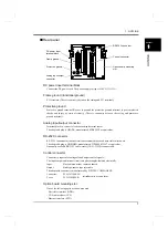
Page 147: ...138 8 SPECIFICATIONS 138 SPECIFICATIONS Chapter 8 8 2 Outside dimensions Unit mm ...

Page 148: ... Port Lithium battery A D Low pass Change Buffer V IN GND F G FRAME Voltage Input for load Voltage input for displacement Pulse input for displacement standard open collector Rotary A B Z COM communications I F VCC DC 24V IN Standard Options Option Mountable shows photocoupler isolation shows pulse transformer isolation One mountable External Voltage Out Filter OFF flash ROM card slot sensor optio...

Page 149: ... Filter P45 Digital Filter P46 Y axis Setting Exc Voltage P40 Unit P40 Zero Cal P40 Equiv Cal P40 Actual Cal P40 Overload P41 Increment P41 Analog Filter P41 Digital Filter P41 DZ Limit P41 Display Range Y Start Point P54 Y End Point P54 X Start Point P55 X End Point P55 Change of Sct P57 Use Sct P57 Use Hold P57 Sct Start End P61 Load HI LO Limit P62 DPM HI LO Limit P62 Measurement Start Start Co...

Page 150: ...nguage P122 Work Protect P122 First Protect P122 Initialization P122 Self Check P122 Analog output filter P124 Password P125 Time Adjust P125 Speed P81 Data Bit P81 Stop Bit P82 Parity Bit P82 Delimiter P82 Header P82 Flow Control P82 Com Mode P82 Reference Wave P67 Compare Area P68 Shift P68 Tie Drawing P69 Compare Margin P69 Relative P70 Relative Point P70 Wave Save P70 Waveform Comparison Setti...

Page 151: ... 99kN N Increment 1 0 1 1 2 2 5 3 10 0 01kN N Analog Filter 0 10 1 30 2 100 3 300 Hz 300Hz N Digital Filter 0 2 to 999 Times 0 Times N DZ Limit 0 to 9999 99 99kN N X axis Setting standard Time DPM Change 0 Time 1 Displacement Time N Phase Select A B Phase 1 Only A Phase A B Phase N Wave Reference 0 Front 1 Back Front N Unit 1 See 9 3 Unit setting list on p 147 mm N Zero Cal 1 0 to 1000000 0 N Equi...

Page 152: ...s 4 10 0 s Time Displacement Change Displacement 0 2000 1 4000 2 6000 3 8000 4 10000 2 0s 60 00mm N DPM Positioning 9999 to 32000 0 00mm N Analog Filter 0 10 1 30 2 100 3 300 Hz 300Hz N Digital Filter 0 2 to 999 Times 0Times N Option Setting Equipment ID 1 0 to 999 0 N Auto Preserv 0 Off 1 On Overwrite 2 On Not Overwrite Off N Preserv of Set 0 All Parameter 1 Comparison Waveform All Parameter Read...

Page 153: ... OFF 1 ON ON N Password 0 to 9999 0 Time Adjust 1 2001 01 01 00 00 00 to 2079 12 31 23 59 59 2001 01 01 00 00 00 S Item Set value Input range display range Initial value Memory 2 Remarks Settings by work Work No 0 to 15 0 Copy No 0 to 15 0 Measurement Start Condition Setting Start Condition 0 Only External Input 1 External Input Load 2 External Input Displacement 2 can be set only when the X axis ...

Page 154: ...400 10 1600 11 1800 12 2000 13 2200 Measurement Length 2000 Displacement Back X axis Start Point 0 25 1 50 2 100 3 200 4 400 5 600 6 800 7 1000 8 1200 9 1400 10 1600 11 1800 12 2000 13 2200 Measurement Length 2000 2000ms S Hold Setting Change of Sct common to all work 0 External Input 1 Setting 0 can be set only when the time or displacement Front Setting S Use Sct 1 to 5 1 S Sct No for RS 232C co...

Page 155: ... Ordinal 1 to 15 Times 1 Times S Interval AB Inflection PointA Inflection PointB 1 to 999 Measurement Length 2000 100ms 100ms S Waveform Comparison Setting Reference Wave Compare Area start point end point Time or displacement Front 0 to 2047 Measurement Length 2000 Displacement Back 2047 to 0 Measurement Length 2000 0 to 2047ms S Shift Range Time or displacement Front 0 to 2047 Measurement Length...

Page 156: ...Nm 29 MPa 46 in 56 mg m 90 A 7 lb 17 mNm 30 GPa 47 ft 57 kg m 91 kA 8 dyne 18 Nm 31 N m2 58 kgm s 92 μV 9 kdyne 19 kNm 32 μbar 59 kgm2 s 93 mV 10 oz 20 MNm 33 mbar 60 kgm2 94 V 21 ftlb 34 bar 61 mPas 95 kV 22 inlb 35 mmHg 62 Pas 96 Ω 23 inoz 36 inH2O 63 m2 s 97 kΩ 37 ftH2O 64 mm s 98 MΩ 38 psia 65 m s 99 W 39 psig 66 mm min 100 kW 40 atom 67 cm min 101 MW 68 m min 102 VA 69 m h 103 70 km h 104 F 7...

Page 157: ...s considered that reversely directed force is applied to the sensor Check around the sensor If such reversely directed force cannot be identified and the error cannot still be removed break s in the cables mistake s in wiring or sensor failure is considered A signal equivalent to a display value beyond 9999 is input It is considered that unexpectedly excessive load is applied to the sensor Perform...

Page 158: ...ge If the setting is such that the signal falls within the signal input range and the error cannot still be removed break s in the cables mistake s in wiring or sensor failure is considered In the case of standard line driver spec The sensor output pulse count is below the F381A internal count range Set so that the sensor output pulse count will not drop below the internal count range Also input t...

Page 159: ...t calibration range Bring the sensor input into the signal input range internal count range Load Make the load indicated value 9999 to 9999 Displacement Make the displacement indicated value 9999 to 32000 Error Error release After the indicated value falls within the set Overload value turn OFF ON the Reset input or press on the Main screen Turn OFF ON the Reset input or press on the Main screen O...

Page 160: ...nnect the output cable properly referring to the equivalent circuit diagram Check to see if the power is on External input output signals require external power supply Turn on the power Are the set data erased when the power is turned off The set data are not erased even if the power is turned off Are the set data erased if no power is applied for a long time The F381A preserves the settings for a...

Page 161: ...000 4 5 A1 EN61000 4 6 A1 EN61000 4 8 A1 CAUTION Since the F381A is defined as open type built in equipment be sure to use it as installed and fixed to a panel etc Use shielded cables for load cell s external input output RS 232C and option s This product is not compliant with the EC Directives when the CC Link option DeviceNet option and or Ethernet option is mounted EMC Directive EN61000 4 5 A1 ...

Page 162: ...tning Surge Immunity is met by the F381A body in combination with a lightning surge protector and a lightning surge protector for LAN At the Ethernet interface use Lightning surge protector PT BE FM and PT 2 PE S 24AC ST are registered trademarks of PHOENIX CONTACT PT BE FM PT 2 PE S 24AC ST DIN rail mount type F381A body D LAN CAT 5E is registered trademarks of PHOENIX CONTACT F381A body Lightnin...

Page 163: ...otector F381A DC IN To the DC 24V power IN OUT D LAN CAT 5E Lightning surge protector for LAN F381A Ethernet Connection D LAN CAT 5E An attached cable apparatus No lightning surge protector is included as standard optionally available Purchase it from PHOENIX CONTACT or us A lightning surge protector for LAN is Please purchase from PHOENIX CONTACT Point ...

Page 164: ......

Reviews: