background image

F340A


DIGITAL INDICATOR


14 Feb. 2012

Rev. 1.38


OPERATION MANUAL

Summary of Contents for F340A

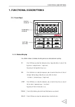
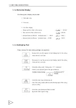
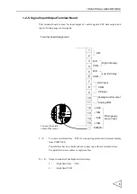
Page 1: ...F340A DIGITAL INDICATOR 14 Feb 2012 Rev 1 38 OPERATION MANUAL...

Page 2: ...te your kind purchase of F340A Digital Indicator To take full advantage of high performance of F340A Thoroughly read this operating manual first before use and understand the explanations contained he...

Page 3: ...urely follow divide into and and are indicated by the following documents Notes indicated here are the serious contents related safely Please use after understanding the contents well WARNING CAUTION...

Page 4: ...or the sensor 10V is set when F340A is dispatched from us Do not disassemble the main body for modifications or repair Be sure to ground the protective ground terminal When smoke a nasty smell or stra...

Page 5: ...minal block Use shielded cables for the connection of strain gauge type sensor displacement sensor External input and output or options Take adequate shielding measures when using at the following loc...

Page 6: ...e Clamp Terminal Block 7 2 2 Connecting Strain Gauge Sensor 8 2 3 Connecting Power Input Terminal 9 2 4 Connecting SI F 10 2 5 Connecting High Low Limit Relays 11 2 6 Connecting Hold and Digital Zero...

Page 7: ...ion 50 5 15 Display Frequency 51 5 16 Excitation Voltage 52 6 HOLD FUNCTION 53 6 1 Peak Hold 53 6 2 Sample Hold Operation Digital Hold 56 7 DIGITAL ZERO FUNCTION 58 8 BCD DATA OUTPUT 59 8 1 Connector...

Page 8: ...ent Output Signal 76 10 2 2 Setting of D A Zero and Gain 76 10 2 3 About D A Resolution 77 10 3 Setting D A Zero Full Scale 78 10 4 About D A Output Error 79 11 DC POWER SOURCE 80 12 OVERSCALE ERROR D...

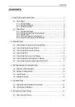
Page 9: ...CONTENTS 15 7 General Specifications 90 15 8 Accessories 91 16 CONFORMITY TO EC DIRECTIVES 92...

Page 10: ...is smaller than the set value of the high limit and larger than the set value of the low limit low limit indicated value high limit LOW This LED turns on when the indicated value is smaller than the...

Page 11: ...nd operations Increments by one the numeric in the blinking digit of the setting item selection or set value Decrements by one the numeric in the blinking digit of the setting item selection or set va...

Page 12: ...ain Forcibly resets the indicated value to zero digital zero function When the calibration LOCK is turned off the digital zero function is not activated using this key External DZ input is also disabl...

Page 13: ...This is a F G terminal of AC input The frame and the F G terminal are conducted 1 2 3 Options Slot One option board can in stall in the option slot BCD Parallel data output BCO RS 232C Interface 232 D...

Page 14: ...splay from UNIPULSE This interface has no polarity and can connect up to three external devices Use parallel two core cables or captire cables 3 6 Output terminals of the high low limit relays 3 High...

Page 15: ...inals for inputting digital zero signals Available in LOCK ON only 9 DZ input 8 COM 10 11 Terminal for output of a voltage proportional to the sensor input Output voltage is approx 2V per 1mV V sensor...

Page 16: ...rewdriver into the upper hole and lift upward 4 Insert the twisted wires into the lower hole 5 Make sure cable is clamped securely and does not come out with a slight tug 0 2in Cable can be from 24 to...

Page 17: ...2 CONNECTION 8 2 2 Connecting Strain Gauge Sensor 4 wire sensor 6 wire sensor EXC EXC SIG SIG SHIELD IN OUT IN OUT 12 13 14 15 F340A EXC EXC SIG SIG SHIELD IN OUT IN OUT 12 13 14 15 F340A...

Page 18: ...n the back of the F340A and its negative side to the black screw side The input voltage is 12V 24V DC Before connecting cables to the terminal block put on climp style terminals M3 to the cables as sh...

Page 19: ...l interface SI F for connecting printers and external display from UNIPULSE This interface has no polarity and can connect up to three external devices Use parallel two core cables or captire cables C...

Page 20: ...ar the load as possible Power Supply Power Supply N O COM Inside Outside F340A Low limit relay Rating is 250V AC and 0 5A Rating is 30V DC and 0 5A CAUTION Overvoltage and overcurrent may cause breakd...

Page 21: ...lay switch Relay Contact Transistor 12V IN IN TTL open 7 8 Outside F340A collect output Hold input Ic Approx 8mA COM Push switch 9 8 DZ input Connect 9 and 8 ON when IN is H CAUTION Avoid applying ext...

Page 22: ...g Analog Monitor Output VOL OUT Terminal for out put of a voltage proportional to the sensor input Output voltage is approx 2V per 1mV V sensor input 10 External device Load resistance 2k or above SIG...

Page 23: ...s Digital Near Zero Digital Filter Analog Filter Motion Detect Motion Detect Zero Tracking Zero Tracking Hold Mode Automatic Printing Hold Value Printing Offset Setting Mode 2 UP DOWN DOWN UP DOWN UP...

Page 24: ...LOCK Scale Display BCD Data Update Rate RS 232C D A Full Scale Setting Mode3 Setting Mode4 UP DOWN Excitation UP DOWN DOWN UP DOWN UP SEL D A Zero Setting Setting Frequency Division Voltage P 49 P 50...

Page 25: ...Motion Detect band 5 Zero Tracking time 6 Zero Tracking band 7 Hold Mode 8 Automatic Printing 9 Hold value Printing Blnking OFF HI OK LOW HOLD PEAK HI OK LOW HOLD PEAK HI OK LOW HOLD PEAK HI OK LOW H...

Page 26: ...tting 3 3 List of Values Setting Mode1 HI OK LOW HOLD PEAK HI OK LOW HOLD PEAK HI OK LOW HOLD PEAK HI OK LOW HOLD PEAK HI OK LOW HOLD PEAK HI OK LOW HOLD PEAK HI OK LOW HOLD PEAK HI OK LOW HOLD PEAK I...

Page 27: ...5 4 Motion Detect band 05 5 Zero Tracking time 0 0 6 Zero Tracking band 00 7 Hold Mode 0 8 Automatic Printing 1 9 Hold Value Printing 0 Item Default Set Value LOCK Calibration LOCK 1 LOCK 0000 2 Scal...

Page 28: ...high low limit and digital offset D A zero setting full scale setting press key SHIFT CAL Set Value is validated Setting Mode is terminated to return to F1 of setting Mode1 is displayed is displayed i...

Page 29: ...e applied For example Gain will be automatically decided by registering the values indicated as follows for load 2 001mV V 100 0kgf for pressure 2 002mV V 10 00kgf cm2 and for torque 2 502mV V 15 00kg...

Page 30: ...input calibration uses the following procedure Release the Calibration LOCK that inhibits calibration Set the minimum value of the digital change desired omissible if no desired value is present Set t...

Page 31: ...de 3 2 Select calibration lock Use and key to set the calibration lock of OFF 0 then use key to validate the setting To return to the indicated value display press key FNC SEL SEL DOWN ENT SEL UP DOWN...

Page 32: ...ange that digit to place a decimal point is set 1 Select setting mode 3 2 Set the scale division Use and keys to set the scale division then use key to validate the setting To return to the indicated...

Page 33: ...the rated value Use and keys to set the rated value then use key to validate the setting Press key at a blinking digit to place a decimal point immediately after the digit 4 Place the sensor without...

Page 34: ...de 3 2 Select calibration lock 3 Use and key to set the calibration lock of ON 1 then use key to validate the setting To return to the indicated value display press key FNC SEL SEL DOWN ENT SEL UP DOW...

Page 35: ...ion Set the minimum value of the digital change desired omissible if no desired value is present Set the zero point of the strain gauge sensor Set the span gain point of the strain gage sensor Set the...

Page 36: ...de 3 2 Select calibration lock Use and key to set the calibration lock of OFF 0 then use key to validate the setting To return to the indicated value display press key FNC SEL SEL DOWN ENT SEL UP DOWN...

Page 37: ...ivision Use and keys to set the scale division then use key to validate the setting To return to the indicated value display press key FNC SEL SEL DOWN ENT Press twice UP DOWN SEL ENT ESC Setting of S...

Page 38: ...Output of the strain gauge sensor is on the minus side Check to see if the SIG and SIG wiring if the sensor is reversed On completion of calibration turn on the calibration LOCK 1 Apply an actual loa...

Page 39: ...e 3 2 Select calibration lock 3 Use and key to set the calibration lock of ON 1 then use key to validate the setting To return to the indicated value display press key FNC SEL SEL DOWN ENT SEL UP DOWN...

Page 40: ...reby the high output is turned on when the indicated value exceeds the high low output is turned on when it drops below the low limit HIGH LOW output conditions HIGH Indicated value High limit value L...

Page 41: ...te the setting 3 Select low limit value Use and key to set the low limit value Press key to place a minus sign Press key to validate the setting To return to the indicated value display press key FNC...

Page 42: ...ree times ENT UP DOWN ENT ESC High Low Limit Comparator Mode High Low Limit 3 Comparison is made at stable 2 Comparison is always made 1 Comparison is made in the 0 Comparison is always made Comparato...

Page 43: ...e comparator is turned off when the indicated value is below the high limit value by the hysteresis setting This is effective in preventing chattering caused when signals are slightly varying vibratin...

Page 44: ...peration High limit Low limit 0 Hysteresis range Time High limit relay HI LED Low limit relay LO LED OK LED Relay ON LED ON Relay OFF LED OFF Relay ON LED ON Relay ON LED ON Relay OFF LED OFF Relay OF...

Page 45: ...e and keys to set the hysteresis range then use key to validate the setting To return to the indicated value display press key FNC DOWN Press four times ENT UP DOWN SEL ENT ESC Setting of Hysteresis H...

Page 46: ...by unloading the equipment for some reason or when you want to give offset Indicated value to be displayed Actual indicated value Digital offset setting value 1 Select setting mode 1 2 Select digital...

Page 47: ...or details see High and Low Limit Comparator Mode on page 33 and Automatic Printing on page 46 1 Select setting mode 1 2 Select near zero Use and keys to set the near zero then use key to validate the...

Page 48: ...s A higher frequency will make a more stable display with slower response A lower frequency will have quicker response but more unstable display 1 Select setting mode 2 2 Select digital filter Use and...

Page 49: ...ass filter cutout freguency is selectable in the 4 10 100 3k Hz 1 Select setting mode 2 2 Select analog filter Use and keys to set the analog filter then use key to validate the setting To return to t...

Page 50: ...efore fall within the specified range and the status last for a specified time indicated values are assumed stable Set 100mSec Time Set period Indicated value range Whether the indicated value is stab...

Page 51: ...date the setting 3 Select motion detect range Use and keys to set the motion detect range then use key to validate the setting To return to the indicated value display press key FNC SEL DOWN Press thr...

Page 52: ...ing Time Use and keys to set the zero tracking time then use key to validate the setting 3 Select zero tracking range Use and keys to set the zero tracking range then use key to validate the setting T...

Page 53: ...dicated value 02 corresponds to 0 5 scales and 12 3 scales If the time is set to 0 0 sec and range to 00 the Zero Tracking function does not work Boundary of zero track BAND COUNT the minimum digital...

Page 54: ...ignal and the Sample Hold function to hold and display an optional point 1 Select setting mode 2 2 Select hold mode Use and keys to set the hold mode then use key to validate the setting To return to...

Page 55: ...bilization is set in the Motion Detect function The stabilized indicated value can be held for three seconds indicated value hold function Operation of the indicated value hold function Indicated Near...

Page 56: ...e 2 2 Select automatic printing Use and keys to set the automatic printing then use key to validate the setting To return to the indicated value display press key FNC SEL DOWN Press eight times ENT UP...

Page 57: ...e 2 2 Select hold value printing Use and keys to set the hold value printing then use key to validate the setting To return to the indicated value display press key FNC SEL DOWN Press nine times ENT U...

Page 58: ...ENT UP DOWN SEL ENT ESC Setting of LOCK 1 LOCK 0 LOCK released Setting Value LOCK 1 LOCK 0 LOCK released Calbration LOCK Zero key operation 1 Invalid 0 Valid Hold key 1 Invalid 0 Valid operation For s...

Page 59: ...gital change 1 Select setting mode 3 2 Select scale division Use and key to set the scale division then use key to validate the setting To return to the indicated value display press key FNC SEL SEL D...

Page 60: ...conversion count is fixed to 100 per second 1 Select setting mode 3 2 Select display frequency Use and keys to set the display frequency then use key to validate the setting To return to the indicate...

Page 61: ...h key To return to the indicated value display press key FNC SEL SEL ENT Press four times DOWN UP DOWN ENT ESC Setting Excitation Voltage Excitation Voltage 1 10 V 0 2 5V CAUTION Use a strain gauge se...

Page 62: ...FUNCTION 53 6 HOLD FUNCTION 6 1 Peak Hold Peak Hold Operation LED lighting Key input HOLD LED HOLD Peak hold start Peak hold reset Time Indicated value Sensor input value Peak hold section Peak hold r...

Page 63: ...6HOLD FUNCTION 54 LED lighting Hold input HOLD LED Time Indicated value Sensor input value Peak hold section Peak hold release Peak hold start Peak hold reset...

Page 64: ...A D conversion of the analog value t3 Time from the input of the hold input ON OFF to the reset of the analog peak hold value t4 The minimum tracking resetting time required for resetting the display...

Page 65: ...e Hold Operation Digital Hold Sample Hold Operation Hold section LED lighting Key input HOLD HOLD LED Hold section LED lighting HOLD LED Hold input Indicated value Sensor input value Time Time Indicat...

Page 66: ...e hold to the A D conversion of the hold value t3 Time from the input of the hold input ON OFF to the reset of the analog hold t4 The minimum tracking resetting time required for resetting the display...

Page 67: ...om the short circuiting of the DZ input OFF ON to when the indicated value becomes 0 t2 Time from the input of the DZ input ON OFF to when the indicated value returns to tracking 1 Perform digital zer...

Page 68: ...8 1 Connector Pin Assignment Amphenol Connector 36 Pin Compatible connector is DDK57 30360 or equivalent No Signal No Signal 1 COM 19 COM 2 Out 1 20 3 Out 2 21 4 Out 4 22 Out Near Zero 5 Out 8 23 Out...

Page 69: ...t open the negative logic is used When COM and pin 28 are short circuited the positive logic is used 8 3 Equivalent Circuit Output The signal output circuit employs the TTL open collector output F340A...

Page 70: ...when LOAD or LOAD and OFL1 or OFL2 are specified Vcc F340A Inside Ic Approx 6mA COM Switch Transistor 5V TTL open collector output Open OFF Short ON Outside CAUTION Avoid applying external voltages t...

Page 71: ...BCD Data Update Rate Selection BCD data OVER strobe range STROBE 0 1 1 Select setting mode 4 2 Set the update rate of BCD parallel data output FNC SEL DOWN ENT BCD Data Update Rate Selection 6 1 time...

Page 72: ...OUTPUT 63 Normaly BCD data update synchronous the A D conversion 100 times sec When the BCD input equipment is low ability and can not read out the high rate of 100 times sec set the BCD data update r...

Page 73: ...h as control aggregation recording and so on 9 1 Communication Specifications 9 1 1 Standard Signal level Based on RS 232C Transmitting distance Approx 15m Transmitting method Asynchronous Full duplex...

Page 74: ...e connect pin to pin DTR to DTR DSR to DSR etc Cables should be prepared after checking connector type and pin assignments of the connected device Adaptable plug 25 pin D sub connector 1 FG 14 2 out T...

Page 75: ...ted value display press key FNC SEL Press three times DOWN ENT Press twice UP DOWN SEL ENT ESC Setting of RS 232C Communication 2 Communication Mode 2 transmits when printed 1 Communication Mode 1 tra...

Page 76: ...3 Communication Mode 2 This mode transmits the indicated values when they are printed 9 4 Communication Format 1 Communication Mode 0 Reading Out the Indicated Value the sign indicated value with 5 di...

Page 77: ...0 0 0 0 0 CR LF 2 1 W 0 0 0 0 0 CR LF 3 1 W 0 0 0 0 CR LF 4 1 W 0 0 0 0 CR LF 5 1 W 0 0 0 0 CR LF 6 1 W 0 0 0 0 CR LF 7 1 W 0 0 0 0 0 CR LF 9 1 W 0 0 0 0 0 CR LF 8 1 W 0 0 0 0 0 Set value Set value Se...

Page 78: ...alibration Sign bit Max 5digits Do not put other than zero into a place which is set zero 0 0 0 0 0 0 0 0 0 0 0 0 0 0 0 0 0 Set value No 0 In signed setting this will be recognized This will be recogn...

Page 79: ...is printed CR CR CR CR CR This is effective only when the calibration This will issue print a command value LOCK is 1 This is effective only when the calibration value LOCK is 1 onto SIF 0 1 2 3 4 5...

Page 80: ...AD OFL S Stable M Not Stable H Hold 1 Priority H O or 2 A Zero Tracking OFF T Zero Tracking ON 3 H High Limit ON L Low Limit ON G High Low Limit OFF N High Low Limit ON F Compare OFF 3 Priority N H or...

Page 81: ...ange of the analog output is from 10 to 10V An analog output from 10V to 10V can be obtained with respect to any digital values set by the D A zero setting and the D A full scale setting functions The...

Page 82: ...o set value and the indicated value to output 10V D A full scale set value Respective set values are inputted by the D A zero and full scale setting functions External equipment Load resistance 2k or...

Page 83: ...1 6000 with respect to 0 to 10V In other words the minimum unit of voltage is 10 to 10V 1 6000 3 33mV Also the minimum unit of indicated value is D A full scale set value D A zero set value 2 1 6000 I...

Page 84: ...e obtained with respect to any digital values set by the D A zero setting and the D A full scale setting functions The output circuit and the main circuit are isolated Current output 4 to 20mA load re...

Page 85: ...ndicated value to output 4mA D A zero set value and the indicated value to output 20mA D A full scale set value Respective set values are inputted by the D A zero and full scale setting functions Exte...

Page 86: ...converter is 1 3000 with respect to 4 to 20mA In other words the minimum unit of voltage is 20 4mA 1 3000 5 33 A Also the minimum unit of indicated value is D A full scale set value D A zero set value...

Page 87: ...put minus sign When you have made setting validate it with key 3 Set D A full scale Set D A full scale with and keys Press key to put minus sign When you have made setting validate it with key FNC SEL...

Page 88: ...t only when D A option is provided D A output is less than the range of output For current output about 0mA or less For voltage output about 12 5V or less The D A output exceeds the range of the outpu...

Page 89: ...340A and its negative side to the black screw side Input voltage range voltage between terminals of the F340A DC12 24V 15 Power consumption 15W max Red Black 1 2 3 4 5 6 7 8 9 10 11 12 13 14 15 DC IN...

Page 90: ...r under 3 2mV V between SIG Plus overflow of the A D converter over 3 2mV V between SIG Indicated value overflowed indicated value 1999 Indicated value overflowed indicated value 1999 Span set value i...

Page 91: ...errors in the internal circuits and in programs and the Visual check Function to visually check the indicator The self check is completed in 30 seconds The display should appear then the indicate val...

Page 92: ...13 SELF CHECK FUNCTION AND INITIALIZATION 83 Self check Visual Check Sequence...

Page 93: ...memory to the factory setting This operation resets all set values except calibrated values obtained through zero calibration and span calibration to the factory setting The initialization follows the...

Page 94: ...13 SELF CHECK FUNCTION AND INITIALIZATION 85 Initialization Sequence...

Page 95: ...fer F G FRAME Serial Port Parallel Port Port Port Serial Port RAM 4Kbyte MPU 16bit Flash ROM 128K Watch Dog NOV RAM 1024bit Display Key Input HOLD DZ 2Line 2Line Parallel SI F D A RS 232C BCD HI LO SI...

Page 96: ...W PEAK HOLD F340A DIGITAL INDICATOR HOLD ZERO ESC DOWN SEL ENT UP FNC SHIFT CAL GAIN OPTION BCO 232 DAC B V 10V 2 5V DIGITAL INDICATOR F340A 100 240V 50 60Hz 15W MADE IN JAPAN SI F HI LO HOLD DZ VOL O...

Page 97: ...V input Zero adjustment range 0 2 0mV V Gain adjustment range 0 5 3 0mV V Analog input signal sensitivity 1 V count Accuracy Non linearity 0 02 FS of 3mV V input Zero drift 0 5 V Gain drift 25ppm A D...

Page 98: ...alibration High limit value Low limit value High Low limit comparison mode Hysteresis Digital offset Near zero Digital filter Analogfilter Motion detect Zero tracking Hold mode Automatic printing Hold...

Page 99: ...24V DC 15 Depending on the request at the time of order Power consumption AC spec 15W max DC spec 15W max Rush current Typ 20A 2 5 msec 100V AC mean load state ordinary temperature at cold start time...

Page 100: ...nal manual 1 DC spec Mini screwdriver for terminal board connection 1 Ferrite core 1 BCD Output connector 1 when BCD option is supplied F340A operational manual 1 About the power cord The power cord a...

Page 101: ...product as standard equipment can be used in the AC100V power supply in Japan Official ratings voltage AC125V Please use the power cable authorized in the country when you use this product outside Ja...

Page 102: ...ng surge protect The cable of the EU outlet shape is required for connection of lighting serge protect Option MAINTRAB MNT 1Dis a trademark of PHOENIX CONTACT MAINTRAB MNT 1D No lightning surge protec...

Page 103: ...IX CONTACT PT BE FM PT 2 PE S 24AC ST DIN rail attachment type 6 4 2 5 3 1 L N IN OUT L N PT 2 PE S 24AC ST PT BE FM Lightning Surge Protector F340A DC IN To the DC 24V power No lightning surge protec...

Page 104: ...Unipulse Corporation 9 11 Nihonbashi Hisamatsucho Chuo ku Tokyo 103 0005 Tel 81 3 3639 6120 Fax 81 3 3639 6130...

Reviews: