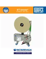
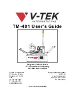
background image

TM-401 User’s Guide

Original Instructions

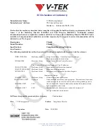
EC Declaration of Conformity 

ISO 9001:2008 Certified


User’s Guide # D292104B

V-TEK, Incorporated

751 Summit Avenue
Mankato, MN  56001
USA
(P) 507-387-2039
(F) 507-387-2257

www.vtekusa.com

European Representative

QNET BV

Hommerterweg 286

6436 AM Amstenrade

The Netherlands

Summary of Contents for TM-401

Page 1: ...ation of Conformity ISO 9001 2008 Certified User s Guide D292104B V TEK Incorporated 751 Summit Avenue Mankato MN 56001 USA P 507 387 2039 F 507 387 2257 www vtekusa com European Representative QNET BV Hommerterweg 286 6436 AM Amstenrade The Netherlands ...

Page 2: ...ovided Material Significant portions of this documentation were provided by KEYENCE CORPORATION OF AMERICA 1100 North Arlington Heights Road Suite210 Itasca IL 60143 1 888 KEYENCE 1 888 539 3623 www keyence com ...

Page 3: ...NISO 12100 2006 Machinery Safety Safety of machinery General principles for design Risk assessment and risk reduction EN13849 2008 Machinery Safety Safety Related Parts of Control Systems Part 1 General Principals for Design and Part 2 Validation EN ISO 13732 2008 Machinery Safety Ergonomics of the thermal environment EN 614 2 2000 A1 2008 Machinery Safety Ergonomic design principals EN 13850 2008...

Page 4: ......

Page 5: ...Introduction Contents Introduction ii Theory of Operation iii Machine Details iv Intended Use v Operator Requirements vii Safety Features viii Safety Warning Labels xi Contact Information xii ...

Page 6: ... and operator intervention for fast easy functioning Standard Features Touch screen operator interface for easy setup and operation Single or Dual Tube input options Ability to rotate components 90 or 180 Output to tape Innovative universal adjustable heat and PSA sealer Software controlled advance movement of carrier tape 2mm to 144mm pitch Adjustable track assembly for tape widths 8mm to 72 mm 2...

Page 7: ...tion stop operation and trigger an error message allowing the user to correct the error before continuing operation As the tape advances it passes sensors which detect jams in tape Once the carrier tape reaches the TM 401 sealer assembly cover tape is applied The part is then sealed in the pocket with either a Heat Seal or Pressure Sensitive Adhesive PSA cover tape When the sealing pro cess is com...

Page 8: ... 35 5 90 cm Working area 11 x 9 3 5 m x 2 75 m Weight 217 lb 98 5 Kg Power Requirements Air consumption 5 SCFM at 85 PSI Electrical 120 240 VAC 50 60Hz AC Note The TM 401 is designed and tested to meet the CE Directives 2006 42 EC 2004 108 EC These tests were conducted with the power requirements of 230V 50Hz However the TM 401 can also handle other voltage levels seen in other parts of the world ...

Page 9: ...n the machine s controller and can be set at any speed from 1 100 percent of maximum speed Feed rates can vary from 2 000 to 2 800 units per hour dependent on component size Caution V TEK Incorporated takes no responsibility for the safety of the TM 401 if it is used for any purpose other than the intended purpose as specified in this User s Guide Operating Environment The TM 401 is designed to be...

Page 10: ...these enclosures or to block disable or override the door sensors The enclosure doors may be left open during basic set up procedures such as positioning the pick head at place or pick locations If the enclosure doors are left open during setup the TM 401 automatically reduces the speed of the pick head to a fraction of its normal operating speed to prevent operator injury due to collision etc The...

Page 11: ...ng the TM 401 Safe operation of the TM 401 does not require gloves of any type however some component manufacturers may recommend gloves be worn when placing parts in tape Consult the compo nent manufacturer for specific placement instructions Ear protection is not necessary during nor mal operation When running the TM 401 the operator should stand or sit in front of the touch screen to assure eas...

Page 12: ...ine will require a reset before operation can continue The emergency stop control circuit removes elec trical power to all motors moving parts heat sources pneumatics and energy storing devices This includes the stepper motor drive stepper motors the servo motor drive servo motors drive circuits the main control board the heat sealer and all pneumatics The only devices that remain powered are the ...

Page 13: ...ision etc System Alarm The system alarm will sound and halt the Run Mode process of the machine at any time a Sys tem Alarm occurs A description of the System Alarm and suggestions for resolving it will appear on the HMI Main Screen Lockout Tagout The Main Switch can be turned ON and OFF by turning the red knob back and forth When the red knob is placed in the OFF position the lockout tagout hole ...

Page 14: ...ber The combination of a solid green light and a solid amber light indicate the machine is at the end of a job and is in the process of creating a leader Red Amber The combination of a blinking red light and a blinking amber light indicates the machine is at the end of a job and attempting to create a leader how ever something has interfered with the process stopping the machine A blinking red lig...

Page 15: ...er to the machine before removing panels or enclosures with this warning label Temperature Hazards Indicates a hot surface Use care when working near these surfaces and allow them to cool before performing maintenance Pinch Hazard Indicates areas where moving parts or doors can pinch fingers if safety precau tions are not observed Consult Manual Consult User s Guide for proper procedure Disconnect...

Page 16: ...ervice vtekusa com website http www vtekusa com For customer service please refer to the Customer Service Contact Sheet at the back of this manual European Representative QNET BV Hommerterweg 286 6436 AM Amstenrade The Netherlands KvK Zuid Limburg 14091511 email qnet ce authorizedrepresentative eu website www ce authorizedrepresentative eu ...

Page 17: ...act Information i xii Table of Contents Chapter 1 Assembly Installation 1 1 Preparing the Work Area 1 2 Space Requirements 1 2 Table Requirements 1 3 Power Requirements 1 4 Unpacking the TM 401 1 5 Assembling the TM 401 1 6 Equipment Required 1 6 Chapter 2 Machine Overview 2 1 Front View 2 2 Right Side View 2 3 Left Side View 2 4 Back View 2 5 Controls Connections Labeling 2 6 The Taper 2 8 Pick P...

Page 18: ...3 Home Motors 4 4 Load the Manual Tube Input Device MTID 4 5 Nozzle Installation 4 7 Selecting the Correct Nozzle Nozzle Tip 4 7 Installing Nozzle Nozzle Tip 4 8 Taper Setup 4 9 Load Carrier Tape 4 9 Load Cover Tape 4 11 Load Take up Reel 4 12 Configure HMI Settings 4 13 Test Seal 4 27 Chapter 5 Vision Setup 5 1 Quick Start Vision Setup 5 2 Connect Vision 5 3 Setup HMI 5 3 Connect Computer 5 5 Con...

Page 19: ... the Job 6 11 Chapter 7 Troubleshooting 7 1 Emergency Stop 7 2 Activating an Emergency Stop 7 2 Clearing an Emergency Stop 7 2 System Alarm Messages 7 6 Error Message Table 7 20 Adjusting Nozzle Vacuum Sensors 7 22 Tips on Part Placement 7 23 Sensor Adjustments 7 26 Adjusting the Low Cover Sensor 7 26 Adjusting the Tape Jam Sensor 7 26 Adjusting Heat Seal Quality 7 27 Heat Seal Shoe Temperature 7 ...

Page 20: ...ssure Regulator 8 4 Pick Head Maintenance 8 5 Nozzle Tip 8 5 Vacuum Levels 8 5 Replace the Vacuum Filter 8 5 Check Actuator Belt Tension 8 7 Taping Module Maintenance 8 8 Heat Sealer 8 8 Loading Track 8 10 PSA Sealer 8 10 Cover Tape Guide 8 10 Appendix A Sensors A 1 Keyence FS V21 FS V22 Sensor Amplifiers A 2 SMC ZSE30 Vacuum Sensor A 4 Spare Parts List Exploded Views Customer Service Contact Shee...

Page 21: ...er 1 Assembly Installation Contents Preparing the Work Area 1 2 Space Requirements 1 2 Table Requirements 1 3 Power Requirements 1 4 Unpacking the TM 401 1 5 Assembling the TM 401 1 6 Equipment Required 1 6 ...

Page 22: ... flat stable surface in a well lit work area that is a minimum of 7 high x 11 wide x 9 deep 2 2 m x 3 5 m x 2 7 m to provide suf ficient space for the assembled machine when it is fully loaded with a variety of tape reel sizes The TM 401 is pictured mounted on the optional 80 20 Frame in the minimum required work area below Minimum Width 11 feet Minimum Height 7 feet ...

Page 23: ...djusted to suit operators of varying heights The objective is to position the TM 401 controls so they are easily accessible for operation and maintenance The suggested level is 36 900 mm above the floor but this may vary from one operator to another The table s working surface should have a slope of no more than 5 degrees Ensure that the TM 401 feet is positioned on a table or the optional 80 20 f...

Page 24: ...pped on the machine from over head Power Requirements The TM 401 will also require access to a 85 110 PSI air pressure system and a 120 240 VAC 50 60 Hz power supply Locate the machine so electrical power cables can be routed away from areas where personnel are expected to move Note It is recommended that cables be routed overhead or underground If cables must be routed over the floor cover them w...

Page 25: ...e Carrier Tape Arm the Take up Assembly the Tower Light and the Spare Parts Kit are individually bubble wrapped and packed around the base machine The TM 401 crate should contain the base machine along with the following items A Carrier Tape Arm B 80 20 Frame optional shipped disassembled C Take up Arm D Laptop Computer optional not pictured A User s Guide Standard and Metric Hex Wrench Sets and a...

Page 26: ...ate on the other side The forklift should only be operated by a licensed certified operator 2 Unpack the Crate a Remove the top and sides from the TM 401 crate Set aside b The TM 401 is shipped partially disas sembled with the Tower Light Take up Arm and Carrier Tape Feed Arm detached and wrapped in bubble wrap Remove the smaller items one at a time from the crate and place on a flat stable surfac...

Page 27: ...sing the lift points illustrated above to safely distribute the machine s weight Lift the machine from the crate and place it onto the prepared work table bench 4 Position the TM 401 in the work area so there is at least 3 feet of clearance on all sides See the Preparing the Work Area section earlier in this chapter for details 5 The TM 401 is shipped with zip ties securing the pick head the 2D Ca...

Page 28: ...04 4 fm Re assemble the TM 401 1 Position the Tower Light Lift Tower Light snapping it in place in an upright position perpendicular to the TM 403 2 Connecting the Carrier Tape Arm a Remove the black knob from the right side of the Track Support Bracket ...

Page 29: ...d secure it into place with the black knob 4 Positioning the Take up Arm a The Take up Arm has a dowel pin which locks into position holes on the Track Sup port Bracket Loosen the black knob on the back of the Take up Arm and position it at about a 45 degree angle from the baseplate assembly Engage the dowel pin into the desired position and secure it into place with the black knob b Plug the elec...

Page 30: ...bled TM 401 verifying that all twist ties have been removed and all cables are secure b Connect the power cord to the power receptacle on the back of the TM 401 then connect the other end to a 120 240 Volt single phase power supply Note It is recommended that the power cord be routed overhead or underground If it must be routed over the floor cover the cords with rubber ramps Protective earth grou...

Page 31: ... 2 Machine Overview Contents Front View 2 2 Right Side View 2 3 Left Side View 2 4 Back View 2 5 Controls Connections Labeling 2 6 The Taper 2 8 Pick Place Assembly 2 10 Tube Feeder 2 11 2D Vision System 2 12 ...

Page 32: ...sion System B Air Regulator I Taper Track C Idler Wheel J Pick Place Head Assembly Bridge D Drive Sprocket K Touch Screen HMI E Cover Tape Arm L Tower Light F Heat PSA Sealer M Blow off Air Pressure Gauge Control G Sensor Amplifiers N Carrier Tape Arm A B D F K J L M N I G C H E ...

Page 33: ...t Side View Chapter 2 TM 401 Overview 2 3 Right Side View A Tower Light E Taper Input B Pick Place Head Enclosure F Tube Feeder s C Carrier Tape Arm G Main Power Switch D Carrier Tape Arm Adjustment Knob C A D G B F F E ...

Page 34: ...w A Pick Place Head Assembly G Take up Arm B Enclosure Doors 3 H Cover Tape Arm C Tube Feeders I Tower Light D Air Regulator J Heat PSA Sealer E Take up Motor Connection K Reset Button F Take up Arm Adjustment Knob L Emergency Stop Switch I H B G L E J C C B F K D B A ...

Page 35: ...Arm C Main Power Switch L Heat PSA Sealer D Fuse Holders Bowl application only M Tube Feeder Power Connection E Pick Head Enclosure N Taper Assembly F Tower Light O Vision Monitor Power Receptacle G Pick Place Head Assembly P Air Pressure Regulator H 2D Vision System Q Take up Arm I Tube Feeder R Power Receptacle A C E D F G I K L B M R Q P H N J O ...

Page 36: ...Connections Labeling Reset Button The TM 401 s blue Reset Button is located on the left side of the machine below the Take up Arm pictured below Emergency Stop Switch The Emergency Stop Switch is located on the left side of the machine below the blue Reset Button pictured above ...

Page 37: ...Arm on the lower sheet metal enclosure Serial Plate This is an example of the Serial Plate which is permanently affixed to the back of the TM 401 It includes basic machine information such as machine weight power usage and short circuit rating The Serial Plate also docu ments machine specific information such as the machine s model name date of manufac ture and unique serial number ...

Page 38: ... D Idler Wheel K Tape Jam Sensor E Sealer Controls Pressure Gauge L Adjustable Width Track F Cover Tape Reel M Carrier Tape Guide G Low Cover Sensor N Carrier Tape Arm Taper Controls A Pick Head Jog Buttons B Take up Tension Control C Sealer Air Pressure Control D Sealer Air Pressure Gauge E Inside Seal Position Lock Adjust A C B E F H I L N G J D M K B A C D E ...

Page 39: ... Idler Wheel G Heat Sealer B Drive Sprocket H PSA Pressure Wheels C Outer Seal Lock I PSA Pressure Adjustment Screws D Outer Seal Adjuster J Cover Tape Guide E Inner Seal Lock K Tape Jam Sensors F Inner Seal Adjust L Cover Tape Width Adjusters A B C G F H I K L E D J K ...

Page 40: ... fm Pick Place Assembly Pick Place Head A Nozzle D Pick Actuator Adjustment Screw B Nozzle Vacuum Sensor E Place Actuator Adjustment Screw C Nozzle Vacuum Filter Pick Place Controls A Blow off Air Pressure Gauge Control B Nozzle Vacuum Sensor A B D E C A B ...

Page 41: ...B On Off Amplitude and Frequency Controls C Feeder D Y Axis Clamping Bolts E Slotted Plate Note Tooling for the Tube Feeder will vary to fit part parameters The TM 401 can be equipped with one or two Tube Feeders as desired A B C D D E B Adjust Feeder position on Slotted Plate D D E ...

Page 42: ...icator C Power I O Connector H Keyence IV G Camera D Ethernet Connector I Lens Cover Focus Ring E M12 Ethernet Cable not shown Note For advanced Vision configuration a computer is required This can be provided by the user or purchased as an option from V TEK Inc System requirements for the vision computer follow Operating system Microsoft Windows 7TM 32 or 64 bit 128 MB RAM 1024 x 768 96 DPI or 12...

Page 43: ...Chapter 3 Human Machine Interface Contents Introduction 3 2 Touch Screen 3 2 HMI Tabs 3 2 Job Tab 3 4 Job Wizard 3 7 Taper Tab 3 18 Head Tab 3 22 MTID Tab 3 26 Run Tab 3 29 ...

Page 44: ...hough only lightly touching the buttons or data fields is necessary for activation the action is referred to as pressing in this manual Note Use care when operating the touch screen and do not use any objects other than a finger to touch the screen A stylus can also be used to click the various buttons HMI Tabs When the TM 401 is powered on the user interface opens to the Job Tab The Job Tab is pi...

Page 45: ...face 3 3 The active tab button is shaded grey In the example on the right the Job Tab is selected Each tab contains a variety of toggle buttons and open fields Press any field to open a numeric or alpha numeric keypad and enter the appro priate information ...

Page 46: ...button at the top of the Tab Menu and the other tab buttons grayed out Homing motors should be done following every system power up or emergency stop Press Home Required to open the Homing Status window Press the Home All Motors button to begin the homing sequence Homing progress is displayed in the Pick Axis Motor Status Bar at the top of the screen ...

Page 47: ... turns from black to green A Homing Succeeded message appears at the end of the sequence If a problem arises during homing the status bar will turn red and a Homing Failed message will appear Pressing the Left Arrow button will open the Run Tab Select the Job Tab from the Tab Menu to navigate back to the Job Tab ...

Page 48: ... move through the job list one job at a time The Page Up and Page Down Arrows buttons to the left of the Job Library are used to move through the job list five jobs at a time The Enter button selects and highlights a job from the Job Library list so it can be opened or saved C The Job Information section has two open fields for entering job information Job Quantity and Job Description Press the fi...

Page 49: ... Job Wizard screen explain each step The Arrow buttons on the bottom of the window move the user forward and backwards through the process Pressing the right Arrow button opens the next Job Wizard screen Pressing the left Arrow opens the previous screen In the first Job Wizard screen the user resets the job to initialize the system Press Reset Job then press the right Arrow key to move to the next...

Page 50: ...eters are set press the right Arrow key to move to the next Job Wizard screen The third Job Wizard step sets up Taper operation A Tape Pitch is determined by the carrier tape selected Use the Pitch Setting Guide on the taper to determine the correct pitch Press the Tape Pitch field to open a keypad and type in the desired value Arrow Buttons Job Wizard Step 2 A B Job Wizard Step 3 C C ...

Page 51: ...ide range of carrier tapes and cover tapes Set tings may vary from one tape product to another The recommended starting point is 90 C The maximum recommended operating temperature is 160 C The temperature for each seal shoe should be increased or decreased as needed after running a peel force test The fourth Job Wizard screen enables or disables the tape Leader A Leader State toggles between ON I ...

Page 52: ...processed If two Tube Feeders are installed this will include the total number of tubes to be processed from both feeders B Enter the maximum number of tubes a single feeder will hold then press the right Arrow Key to move to the next Job Wizard screen The sixth and seventh Job Wizard screens are used to automatically determine Tube Pitch A B Job Wizard Step 5 A C Job Wizard Step 6 B ...

Page 53: ...w match the Current Position and the Learn button will turn green and update to read Learned see Step 7 below Press the right Arrow to move to the next Job Wizard screen A Center the Pick Head over the last track pocket using the Jog buttons To see an illustration of the correct head placement push the Help icon B The distance the head moves with each Jog is set in the Head Jog Step field C Press ...

Page 54: ...shown below A Press Pick Extend Pick Retract to lower the Nozzle to the tube pocket Follow the directions in Chapter 4 Setup for manually adjusting the Pick Actuator to set the correct Nozzle Height Press the right Arrow Key to move to the next Job Wizard screen A Press Pick Part to activate the nozzle and pick a part Job Wizard Step 8 A A B Job Wizard Step 9 ...

Page 55: ...low the user to jog the Pick Head and Carrier Tape forward or backward in small preset increments This is useful for centering the Nozzle in the pick and place positions The Up Down Arrow keys move the Pick Head forward and backward The Left Right Arrow keys move the tape left and right in the Taper Track B Enter the value in millimeters for the Head Jog Step and Taper Jog Step fields C Pressing S...

Page 56: ...xtend and Place Retract Once Place Extend has been pressed the button will change to Place Retract Follow the directions in Chapter 4 Setup for manually adjusting the place Actuator to set the correct Nozzle Height at the Place position Press the right Arrow Key to move to the next Job Wizard screen A Enter the placement angle which was manually set in Step 8 The options are 0 90 and 90 A Job Wiza...

Page 57: ...ted 90 degrees clockwise prior to placement If rotation is set at 90 the part will be rotated 90 degrees counter clockwise prior to placement Press the right Arrow Key to move to the next Job Wizard screen A Test the job settings using the Pick Part and Place Part buttons to pick and place parts B If adjustment are required use the left Arrow key to return to the desired step and adjust settings u...

Page 58: ...ace point and the Inspection point in the Parts Until Inspection field Begin the count with the Place position as 0 so the Place pocket is not included in the count Press the right Arrow Key to move to the final Job Wizard screen A Browse through the Job Library using the Up Down Arrow keys to move up or down through the list To select a Job Name from the list press the Enter key A B Job Wizard St...

Page 59: ...ll overwrite the information stored for the currently selected job Therefore it is important to select the desired job prior to pressing the Save button B Press the Save button to save job settings to the selected job name C Press Finish to close the Job Wizard and return to the Job Tab ...

Page 60: ...et between 1 10 Tape Pitch is determined by the carrier tape selected Use the Pitch Setting Guide on the taper to determine the correct pitch Jog Step sets the distance in millimeters the carrier tape will move forward or back ward each time a Jog button is pressed Note The Jog Step field requires the value to be entered in the following format XX XX i e 60 00 C The Jog buttons in the Index Settin...

Page 61: ...toggles between ON I and OFF O The Parts Until Inspection value is the number of pockets between the Place point and the Inspection point Begin the count at the Place position at zero so the Place position is not included B Pressing the Trigger button triggers the 2D Camera to inspect the part which is currently at the Inspection point The box to the right of the Trigger button will dis play a gre...

Page 62: ... this field The Manual Seal button activates the sealer to perform one seal B The Set Point field allows the user to select the Heat Sealer set point or target temperature Press the field to open the keypad then enter the desired tempera ture in degrees Celsius The Measured field shows the current Heat Sealer temperature in degrees Cel sius Note The TM 401 accommodates a wide range of carrier tape...

Page 63: ...tting for the Tape Jam Sensor is ON The Low Cover Sensor ON I or OFF O button turns the Low Cover Tape Sen sor on and off The Low Cover Tape Sensor detects when the cover tape reel is running low When the Low Cover Tape Sensor is activated an error message appears on the HMI screen The recommended setting for the Low Cover Tape Sensor is ON Note The Low Cover error message is only displayed once d...

Page 64: ...b Menu to open that tab window B The Move To Pick button moves the head to the preset Pick Positions The Move To Place button moves the pick head to the preset Place Position The Pick Part button moves the head from its current location and picks a part from the programmed pick location It then returns the nozzle to its Ready retracted position The Place Part button moves the head from its current...

Page 65: ... Set Place button saves the current position as the place position If the position has been learned the status color after the button will appear green If not learned the status color will appear red In the screen above both the Pick Position and the Place Position have not been learned B The Jog buttons jog the head forward or backward along the X Axis forward backward Head Speed is a percentage ...

Page 66: ...k Extend Pick Retract button actuates the pick solenoid to enable the operator to set the pick height The Rotate Part button rotates the pick head to the preset rotation angle The Place Extend Place Retract button actuates the place solenoid to enable the operator to set the place height B The Part Placement Rotation Angle is manually set during machine setup The options are 0 90 and 90 Head Scree...

Page 67: ... will be rotated 90 degrees counter clockwise prior to placement Nozzle Blow Off Time is the amount of time in milliseconds that the nozzle will activate the blow off pressure to place a part in the Taper C Press the left Arrow button to return to the second Head Setup screen or press a button on the Tab Menu to move to a new tab Note The TM 401 will use these settings for the current job To save ...

Page 68: ...e feeder Number Of Tracks Per Feeder is the total number of tubes that can be pro cessed by a single tube feeder For example if the system has two Tube Feeders that are equipped with eight track tooling the Total Number Of Tubes would be eight However the Number Of Tubes To Process could be as high as 16 Note The MTID does not need to be fully loaded to operate However if If only one tube is loade...

Page 69: ...istance in millimeters that the head will move when Jog is pressed Note Enter Jog Step field values in the following format XXX XX i e 100 00 The Head Position indicates where the pick head is located in relation to the Home position The Learned Position indicates the current Pick position C Press the Cancel button to return to the MTID Tab Once the Learn button has been pressed the Cancel button ...

Page 70: ...XX i e 100 00 The Head Position message indicates where the pick head is located in relation to the Home position The Learned Position indicates the current Pick position C Press the Cancel button to return to the MTID Tab Once the Learn button has been pressed the Cancel button disappears Pressing Learn saves the current head position as the programmed pick location This is the position the pick ...

Page 71: ...lds Quantity and Job Description This information was entered in the Job Wizard during job setup The Job Description field is greyed out indicating it cannot be altered in this tab To edit the Quantity field press anywhere inside the field to open a keypad for data entry C There are four control buttons on the Run Tab Run Running Stop Stopped Reset Job and System Homing The Run and Stop buttons st...

Page 72: ...d be done once following every system power up When System Homing is selected the Homing Status window will appear Pressing the Home All Motors button begins the homing sequence Homing progress is displayed in the Pick Axis Motor Status Bar As the homing sequence is completed the bar gradually turns from black to green A Homing Succeeded message appears at the end of the sequence ...

Page 73: ...e Statistics section keeps a running tally of the current job s Parts Placed Run Time and Parts Per Hour E Status Messages only appear when conditions exist which require the user s attention before the job can be run If the preset quantity of parts has been processed the End Of Job message will appear If the doors are open the Doors Open message will appear The current software version is display...

Page 74: ...3 32 TM 401 User s Guide Run Tab D292104 6 fm ...

Page 75: ...me Motors 4 4 Load the Manual Tube Input Device MTID 4 5 Nozzle Installation 4 7 Selecting the Correct Nozzle Nozzle Tip 4 7 Installing Nozzle Nozzle Tip 4 8 Taper Setup 4 9 Load Carrier Tape 4 9 Load Cover Tape 4 11 Load Take up Reel 4 12 Configure HMI Settings 4 13 Test Seal 4 27 ...

Page 76: ...otors Press Home Required and Home All Motors 3 Load the Manual Tube Input Device MTID Ensure the correct Tooling for the part size to be processed is installed Load components into the Tube Feeder 4 Install Nozzle Ensure correct nozzle size and tip are installed 5 Load Taper Load carrier tape Load cover tape Place an empty reel on the Take up Arm 6 Configure HMI settings Go to the Job Tab and run...

Page 77: ...he machine There will be a brief popping sound as the Air Dump Valve releases air to the machine As the TM 401 powers up the PLC Servo Drivers and HMI Monitor will boot up On top of the machine the Tower Light will flash red indicating the machine is on but not running Note The boot up process takes approximately 90 seconds The monitor will display the HMI Job Tab with a red Home Required message ...

Page 78: ...otors whenever it is required Once the motors have been homed they remain homed until the machine is powered down or the E Stop is activated 1 Press the red Home Required button at the top of the Tab Menu 2 The TM 401 motor homing sequence begins with the pick head moving slowly to the right towards the taper X Axis movement When the head has stopped moving homing is complete Step 2 Home Motors ...

Page 79: ...the feeder plugging the end of the tubes before removal B Using a 9 64 Hex wrench remove the 2 socket head cap screws in the Tooling Platform C Remove the Tooling Platform D Insert the correct Tooling Platform positioning it on the dowel pins to ensure correct placement E Insert the 2 socket head cap screws and tighten in place 2 Loosen the Clamping Bolts on the bottom of the MTID and move the Slo...

Page 80: ...the tubes that are loaded The minimum number of tubes is one Note The TM 401 is designed to work with one or two MTIDs If two MTIDs were included with this TM 401 install them both at this time 4 Turn the Vibratory ON 5 Adjust the Vibratory Frequency speed and Amplitude strength Controls as needed Parts should feed fluidly but not so rapidly that it causes parts to begin jumping around Step 3 Setu...

Page 81: ...ange of sizes and style Contact V TEK Service for information on ordering additional Nozzle Tips Selecting the Correct Nozzle Nozzle Tip To achieve the best picking results select the largest cup size the part can accommo date Maximizing the cup size gives the vacuum access to more surface area which increases its pick up capability The goal is to use a nozzle cup that is just slightly smaller tha...

Page 82: ...he Pick Place Assembly Store the unused Nozzle Shank and Nozzle Cup in the Spare Parts Kit 5 Select the correct Nozzle Shank and Nozzle Cup for the part that will be run Press the Nozzle Cup onto the Nozzle Shaft 6 Insert the Nozzle Shank into the Actuator Shaft in the Pick Place Assembly Note When positioning the Nozzle Shank push it all the way up to the Actuator Shaft then pull it back slightly...

Page 83: ...ommodate the following tape widths 8mm 12mm 16mm 24mm 32mm 44mm 56mm and 72mm The track can be adjusted by sliding the outer track outward until it reaches the correct indentation Check that the taper is set at the correct width for the carrier tape If not pull the front track out until it clicks into the correct position 2 Once the track is adjusted use a strip of the carrier tape as a test to de...

Page 84: ... tape again cutting through a sprocket hole at a 45 angle so the tape feeds easily 5 Guide the carrier tape under the Carrier Tape Guide and then feed it through the carrier tape channel under the taper Note A sharp instrument such as a pair of tweezers may aid in guiding the carrier tape into the loading track 6 Continue to guide the carrier tape forward through the loading track and the sealer u...

Page 85: ...off the spindle 3 Check that the cover tape guide width is adjusted correctly for the cover tape that will be used Pull the cover tape down and compare it to the current setting If the guide is set too wide or too narrow loosen the red knob set screw and pull or push the guide in and out until it matches the width of the cover tape with only a slight amount of extra room 4 If the cover tape is PSA...

Page 86: ...arrier tape and its diameter should be large enough to accommodate the number of components in the taping job 2 The Take up Tension Control is located on the front of the Heat Sealer enclosure next to the Seal Pressure Gauge Control Adjust the take up tension to a rate that suits the weight of the parts that are being processed adjusting it so the take up motor pulls the sealed tape gently forward...

Page 87: ...ob Wizard leads the user through the HMI setup process 1 OPEN JOB WIZARD a Open the HMI Job Screen b Press the Job Wizard button to open the Job Wizard 2 RESET JOB a Press Reset Job to initialize system for Job Wizard b Press the right Arrow key to open the next Job Wizard screen Step 6 Setup HMI ...

Page 88: ...ure HMI Settings D292104 7a fm 3 ENTER JOB PARAMETERS a Enter Job Quantity b Enter Job Description Press the right Arrow key to open the next Job Wizard screen 4 TAPER SETUP Enter Pitch Seal Type and Dwell Time Step 6 Setup HMI TAPER ...

Page 89: ...mmended operat ing temperature is 160 C The temperature for each seal shoe should be increased or decreased as needed after running a peel force test d Set the heat shoe Seal Pressure to the appropriate setting This setting controls the amount of force applied when the sealer shoes drop The recommended starting point is 50 psi e Press the Continuous Advance button The taping module will begin the ...

Page 90: ...misaligned continue adjusting the cover tape guide until it is aligned properly 5 CREATE TRAILER optional The term leader and trailer refer to the lengths of empty carrier tape required at the beginning leader and the end trailer of the finished reel of placed parts Therefore when the reel is being taped on the TM 401 the trailer is the first length of empty carrier tape run before the first part ...

Page 91: ...2104 7a fm Configure HMI Settings Chapter 4 Setup 4 17 6 ENABLE LEADER a Select Leader State and enter Leader Length if enabled b Press the right Arrow key to move to the next screen Step 6 Setup HMI TAPER ...

Page 92: ...d screens are used to detect Tube Pitch and enter the number of tubes that will be loaded in the MTID a Enter the number of tubes that will be processed b Enter the number of tracks in the feeder Press the right Arrow Key to move to the next Job Wizard screen to automatically calculate Tube Pitch Step 6 Setup HMI TUBE FEEDER ...

Page 93: ...e center of the first tube pocket d Press Learn then press the right Arrow key to move to the next screen e Use the Jog controls to position the nozzle over the center of the last Tube pocket Press Learn then press the right Arrow key to move to the next screen 1st Pocket Last Pocket Step 6 Setup HMI TUBE FEEDER ...

Page 94: ...g the Jam Nut on top of the Actuator Adjustment Screw with an 8mm open ended wrench Raise the Nozzle until it is at a safe height so it will not collide with the current part when extended e Tighten the Jam Nut f Press the Pick Extend button g Loosen the Jam Nut on top of the Actuator Adjustment Screw again then lower the Nozzle until it is barely touching the part in the Pick Location h Tighten t...

Page 95: ...w Key to move to the next Job Wizard screen 9 Nozzle Setup Manual Rotation a Press Pick Part to activate the Pick Head and pick a part from the Pick location b If the part needs to be rotated before it is placed in tape Press Rotate Part This will rotate it 90 If no rotation is required for part placement skip this step c Press the right Arrow Key to move to the next Job Wizard screen Step 6 Setup...

Page 96: ...osition The Up Down Arrow keys move the Pick Head forward and backward The Left Right Arrow keys move the tape left and right in the Taper Track b When the Nozzle is centered over the tape pocket press Set Place Position to set the position c Press the right Arrow Key to move to the next Job Wizard screen 11 Set Place Nozzle Height The Pick Head s Z Axis up down position needs to be Step 6 Setup H...

Page 97: ...old the Actuator Adjustment Screw in place from the bottom while loosening the Jam Nut on top of the Actuator Adjustment Screw with an 8mm open ended wrench Lower the Nozzle until the part is barely touching the top of the pocket in the Place Location c Tighten the Jam Nut d Press Place Retract to retract the Nozzle to a safe height e Press the right Arrow Key to move to the next Job Wizard screen...

Page 98: ...ion is set at 0 the part will be placed in the same orientation as it was picked If rotation is set at 90 the part will be rotated 90 degrees clockwise prior to placement If rotation is set at 90 the part will be rotated 90 degrees counter clockwise prior to placement b Press the right Arrow Key to move to the next Job Wizard screen Step 6 Setup HMI NOZZLE 90 0 90 Rotation Options ...

Page 99: ... left Arrow key to return to the desired step and adjust settings Press the right Arrow Key to move to the next Job Wizard screen Note Manually placed parts will be counted in the current job 14 Vision Settings a Set Camera State to ON I or OFF O b If camera is enabled enter number of Parts Until Inspection do not include part at Pick point Press the right Arrow Key to move to the final Job Wizard...

Page 100: ...Job Name from the list press the Enter key Note The Save function will overwrite the information stored for the currently selected job Therefore it is important to select the desired job prior to pressing the Save button b Press the Save button to save job settings to the selected job name then press Finish to close the Job Wizard and return to the main Job Tab Step 6 Setup HMI SAVE SETTINGS ...

Page 101: ...h the carrier tape The cover tape should run exactly in the groove of the cover tape guide and the seal should appear as a solid consistent line If the seal width is incorrect stop the Taper by pressing the Continuous Advance button again 3 Adjust the seal positions as necessary The sealer s inside and outside seals are independently adjustable If one of the seals needs to be moved loosen the corr...

Page 102: ...ove the guide closer to the machine Adjust the Inner Seal Adjust and the Outer Seal Adjust to the desired position then tighten the Position Locks to secure them 4 Perform a Seal Test The V TEK PT 55 Peel Force Tester is pictured on the right Sold separately Proceed to Chapter 5 Vision Setup to configure the Vision System for operation Step 7 Seal Test ...

Page 103: ...ision Setup Contents Quick Start Vision Setup 5 2 Connect Vision 5 3 Setup HMI 5 3 Connect Computer 5 5 Connect Keyence Monitor 5 9 Configure Inspection 5 10 Configure Computer 5 10 Configure Keyence Monitor 5 28 ...

Page 104: ...ied computer only 2 Connect Vision Computer Monitor to Camera 3 Configure Inspection If the optional laptop was purchased for vision configuration V TEK Inc recommends users create a computer Recovery Disk prior to operation and conduct periodic back ups as needed Visit the computer manufacturer s website for instruc tions on creating a recovery disk V TEK Inc does not create or maintain recovery ...

Page 105: ...bit 128 MB RAM 1024 x 768 96 DPI or 1280 x 1024 120 DPI display Ethernet port If vision is enabled for a job the vision computer monitor must be connected to the Key ence IV G Camera and the camera must be trained to inspect the part before the job can be run Setup HMI Follow the steps below to enable Vision Inspection on the TM 401 1 On the TM 401 HMI open the Taper Tab Press the right Arrow butt...

Page 106: ...hen the software installation screen appears follow the prompts to install the Keyence software Note Keyence IV G Software is automatically installed if using the optional V TEK laptop or Keyence IV G Monitor If using one of these options skip this step and proceed to Configure Inspection 4 On the TM 401 HMI select the Taper Tab then press the Right Arrow key to advance to the second Taper screen ...

Page 107: ...he vision computer Proceed to the next section if using the Keyence Monitor instead of a computer 1 Open the Control Panel then select Network and Sharing Center In the Connect or Disconnect section click Local Area Connection 2 The Local Area Connection Status window will open Click Properties Step 1 Vision Setup CONNECT LAPTOP ...

Page 108: ... 6 TM 403 User s Guide Connect Vision D292104 16 fm 3 Double click Internet Protocol version4 TCP IPv4 4 Ensure Obtain an IP address automatically is selected Click OK Step 1 Vision Setup CONNECT LAPTOP ...

Page 109: ...a stored inspection or configure a new inspection open the Keyence Inspection System software by double clicking on the IV Navigator icon on the desktop 6 Select Direct Connection 7 The following pop up will appear Press Connect Step 1 Vision Setup CONNECT LAPTOP ...

Page 110: ...5 8 TM 403 User s Guide Connect Vision D292104 16 fm A Connecting to Sensor status window will open 8 Once the connection is complete the Run Program window will open Step 1 Vision Setup CONNECT LAPTOP ...

Page 111: ...tor s Ethernet cable to the Ethernet port on the back of the TM 401 A 2 Connect the Monitor s power cable to the power connection on the back of the TM 401 B 3 Turn the TM 401 ON The Keyence Monitor will automatically start and open the Keyence software program 4 Select Direct Connection then press Connect to establish a connection between the Keyence Monitor and the Keyence Camera Step 1 Vision S...

Page 112: ...oration of America In order to use the Keyence IV Vision System the camera must be configured and set to Run Mode in the Keyence HMI as well as being enabled on the TM 401 HMI Please complete the following instructions to cor rectly configure the vision system Configure Computer 1 Once the connection is complete the Run Program window will open Select Program ...

Page 113: ...Setup 5 11 2 Click Trigger ON then center a part under the camera 3 Select or create a program from the Program drop down menu A yellow Selection Box will appear over the part image 4 Click NAVI Sensor Setup Step 2 Vision Setup CONFIGURE COMPUTER ...

Page 114: ...5 12 TM 403 User s Guide Configure Inspection D292104 16 fm 5 The Image Optimization window will open Select the Trigger Options button on the right Step 2 Vision Setup CONFIGURE COMPUTER ...

Page 115: ...h a 0ms Trigger Delay 6 Select the Brightness Adjustment button on the right Set the Imaging Mode to High Gain then click the Automatic Brightness Adjustment button Adjust the Exposure Time as needed to achieve the best contrast between the laser mark and the part Step 2 Vision Setup CONFIGURE COMPUTER ...

Page 116: ...the Automatic Focus Adjustment button One or more yellow dots may appear above the Undo button representing the best focus point s Click on the yellow dot s to jump to the associated focus point and select the best one Adjust Focus Position as needed using the plus minus buttons Step 2 Vision Setup CONFIGURE COMPUTER ...

Page 117: ...5 Setup 5 15 8 Select the Extended Functions button on the right Click on the Imaging Area tab not shown and adjust the selection box so it captures the minimum area needed to achieve the desired inspection Step 2 Vision Setup CONFIGURE COMPUTER ...

Page 118: ...pection D292104 16 fm Click on the Lighting tab and select ON and Flash Then click the Next to STEP2 button which is located in the bottom right corner of the window 9 The Save Master window will open Step 2 Vision Setup CONFIGURE COMPUTER ...

Page 119: ...m Configure Inspection Chapter 5 Setup 5 17 Select Register Live image as master Select Register the image Once the image has been registered click OK Then click Next to STEP3 Step 2 Vision Setup CONFIGURE COMPUTER ...

Page 120: ...5 18 TM 403 User s Guide Configure Inspection D292104 16 fm 10 The Tool Settings window will open Select Add Tool Step 2 Vision Setup CONFIGURE COMPUTER ...

Page 121: ...D292104 16 fm Configure Inspection Chapter 5 Setup 5 19 Select the Outline tool then click OK A green outline will now appear around the selected mark Click OK Step 2 Vision Setup CONFIGURE COMPUTER ...

Page 122: ...5 20 TM 403 User s Guide Configure Inspection D292104 16 fm The Tool Settings Options will now appear as below Step 2 Vision Setup CONFIGURE COMPUTER ...

Page 123: ...m Configure Inspection Chapter 5 Setup 5 21 Adjust the yellow Selection Box so it surrounds the selected mark In the Fine Tune Outline section click the Remove Outline button Step 2 Vision Setup CONFIGURE COMPUTER ...

Page 124: ...he Eraser appears as a white square on the image Adjust eraser size as needed then click and drag it over any unwanted data that is outlined in green on the image Reduce Eraser size to remove any smaller green spots of unnecessary data Click OK to finalize edit Step 2 Vision Setup CONFIGURE COMPUTER ...

Page 125: ...tion Chapter 5 Setup 5 23 Click Live Adjustment and the sensor will continuously take measurements Adjust the threshold to yield the highest difference between good and bad parts then click OK Step 2 Vision Setup CONFIGURE COMPUTER ...

Page 126: ... D292104 16 fm 11 The Output Assignment window will open Set up the Outputs as shown below Set OUT1 to Total Status Set OUT2 to Tot StatusNG Set all remaining output to OFF Set Trigger Error Output to Disable Step 2 Vision Setup CONFIGURE COMPUTER ...

Page 127: ... Complete to return to the Run Program window Select Run 13 Click the Manual Trigger button which is located under the Program button to test the inspection criteria The test results will appear on the right side of the window Step 2 Vision Setup CONFIGURE COMPUTER ...

Page 128: ...On the TM 401 HMI open the Taper Tab Press the right Arrow button to advance to the second Taper screen Press Trigger to manually trigger an inspection of the part under the camera The green PASS message should appear Test several good parts to ensure TM 401 correctly and consistently passes good parts Step 2 Vision Setup CONFIGURE COMPUTER ...

Page 129: ...ext trigger inspections with parts which are incorrectly oriented badly marked or with an empty pocket to ensure that they generate a red FAIL message The TM 401 is now ready for operation Select the Run Tab to run the job Step 2 Vision Setup CONFIGURE COMPUTER ...

Page 130: ...e displayed with a blue frame 4 Tool window Displays the tool window which has been set 5 Search Window If the search window of the tool is set the range will be displayed with a light blue frame 6 MENU OFF button Changes the screen from Menu ON to Menu OFF 7 Status gauge Displays the result OK NG of the tool selected 9 OK NG display Displays the total status result 10 Processing time Displays the...

Page 131: ...e 7 MENU OFF button Changes the screen from Menu ON to Menu OFF 8 Status gauge Displays the result OK NG of the tool selected 9 OK NG display Displays the total status result 10 Processing time Displays the time from receiving a trigger until the result is output 11 Image Type display Displays the situation of the screen Run mode or Test mode 12 Trig button Displayed when the external trigger is s...

Page 132: ...plays the Sensor Image Memory screen 17 USB memory button Displays the USB memory screen 18 Sensor setup button Stops running mode and displays the Sensor setup menu screen Program Job Start Navigator 1 Touch the Sensor setup button 2 Touch the Start button Step 2 Vision Setup CONFIGURE MONITOR ...

Page 133: ...D292104 16 fm Configure Inspection Chapter 5 Setup 5 31 Setup Image Optimization 1 Touch Trigger Options 2 Select the External Trigger type Touch OK Step 2 Vision Setup CONFIGURE MONITOR ...

Page 134: ...ustment Touch OK 4 Touch Focus Adjustment If Auto focusing is selected the focus position is adjusted automatically If Manual focusing is selected the focus indicator will be displayed Adjust focus as desired Touch OK 5 Touch Next to proceed to STEP2 Step 2 Vision Setup CONFIGURE MONITOR ...

Page 135: ...age 1 After setting the image optimization press Register Live Image as Master 2 Image the target and touch the Trig button 3 Check the image displayed on the monitor and touch the Register button Touch OK 4 Touch Next to proceed to STEP3 Step 2 Vision Setup CONFIGURE MONITOR ...

Page 136: ...5 34 TM 403 User s Guide Configure Inspection D292104 16 fm Setup Outline Detection Tool 1 Touch the Add Tool button 2 Select Outline 3 Touch Edit Window Step 2 Vision Setup CONFIGURE MONITOR ...

Page 137: ...hapter 5 Setup 5 35 4 Set the position size and the angle of the tool window The detected outline will be displayed in green After the setting is completed touch OK 5 Touch the Limit Adjustment button Step 2 Vision Setup CONFIGURE MONITOR ...

Page 138: ...m 6 Set the threshold to judge OK and NG 7 The display will return to the main screen for the Outline tool 8 Touch OK then touch Next to proceed to STEP4 Setup Area Detection Tool 1 Touch the Add Tool button 2 Select Area Step 2 Vision Setup CONFIGURE MONITOR ...

Page 139: ...16 fm Configure Inspection Chapter 5 Setup 5 37 3 Touch Edit Window button 4 Set the position size and the angle of the tool window After the setting is completed touch OK Step 2 Vision Setup CONFIGURE MONITOR ...

Page 140: ...er s Guide Configure Inspection D292104 16 fm 5 Touch the Brightness Extraction button 6 Touch the brightness area to be the reference of judgment for the Area tool then touch OK Step 2 Vision Setup CONFIGURE MONITOR ...

Page 141: ... 5 39 7 Touch the Limit Adjustment button 8 Set the threshold to judge OK and NG then touch OK The display will return to the main screen for the Color Area Area tool 9 Touch OK then touch Next to proceed to STEP4 Step 2 Vision Setup CONFIGURE MONITOR ...

Page 142: ...03 User s Guide Configure Inspection D292104 16 fm Setup Position Adjust Detection Tool 1 Touch the Add Tool button 2 Touch the Pos Adj button 3 Touch the Edit Window button Step 2 Vision Setup CONFIGURE MONITOR ...

Page 143: ...re Inspection Chapter 5 Setup 5 41 4 Set the position size and the angle of the tool window The detected outline will be displayed in green Touch OK 5 Touch the Limit Adjustment button Step 2 Vision Setup CONFIGURE MONITOR ...

Page 144: ...udge OK and NG 7 After the setting is completed touch OK The display will return to the main screen for Position Adjustment tool 8 Touch OK again then touch Next to proceed to STEP4 Setup Output 1 Touch the output line to assign the output function Step 2 Vision Setup CONFIGURE MONITOR ...

Page 145: ...nfigure Inspection Chapter 5 Setup 5 43 Set the output functions as follows OUT1 Busy OUT2 Total Status OUT3 OUT8 OFF 2 After the setting is completed touch Complete then touch Yes Step 2 Vision Setup CONFIGURE MONITOR ...

Page 146: ...5 44 TM 403 User s Guide Configure Inspection D292104 16 fm ...

Page 147: ...rt Running a Job 6 2 Preparing to Run a Pre programmed Job 6 4 Power up the System 6 4 Home Motors 6 4 Setup the Manual Tube Input Device MTID 6 6 Setup the Taper 6 7 Select Job 6 8 Setup the Pick Head 6 9 Setup Vision 6 10 Run the Job 6 11 ...

Page 148: ...on the HMI and select Home Motors 3 Setup Manual Tube Input Device MTID Ensure the correct tooling is installed on the MTID for the components that will be processed Load components Turn Vibratory ON Adjust Amplitude and Frequency for proper feeding 4 Setup Taper Ensure sufficient carrier tape and cover tape are loaded to complete the job Load an empty take up reel Run peel force test to verify se...

Page 149: ...b on the HMI and advance to the second screen Ensure camera is enabled Configure inspection as needed Note To configure vision inspection see Chapter 4 Setup 8 Run the Job On the HMI select the Run Tab then press Run Load unload parts and reels as needed Caution V TEK Incorporated takes no responsibility for the safety of TM 401 if it is used for any purpose other than the intended purpose as spec...

Page 150: ...er up the System 1 Power up the machine by turning the Main Power Switch which is located on the right side of the machine to the ON position 2 Press the blue Reset button on the left side of the machine Home Motors Note The TM 401 only needs to be homed once after each power up or emer gency stop Once the motors have been homed they remain homed until the machine is powered down 1 The HMI will op...

Page 151: ...r X Axis movement The homing sequence will continue until the nozzle has risen to its highest position and then returned to home and the head has moved all the way to the right and then returned to home Homing progress is displayed as a green bar in the Pick Axis Motor field of the Homing window Once the nozzle and head have stopped moving homing is complete A Homing Succeeded message will appear ...

Page 152: ...ick position 3 Load filled tubes into feeder Note The TM 401 is designed to work with one or two MTIDs installed Follow the setup procedures for both MTIDs if the optional second feeder is installed 4 Turn the Vibratory ON and set Vibratory Off Delay 5 Adjust the Vibratory s Amplitude and Frequency controls as needed to feed selected parts smoothly Step 3 Setup MTID Y Axis Clamping Bolts Adjust fe...

Page 153: ...elect PSA or Heat seal 3 Align cover tape with carrier tape 4 Run a pull test and adjust seal strength as needed 5 Place an empty reel onto the take up reel spindle 6 Use the Continuous Advance button on the Taper Tab to run out the tape until it can be attached to the reel The tape normally can be attached by inserting it into the reel hub or with adhesive tape Step 4 Setup Taper ...

Page 154: ...up and saved in the machine s memory the first step in running the job is to call it up with the Job Select screen 1 On the HMI select the Job Tab 2 Browse through the Job Library to locate the desired job by using the up and down Arrow buttons 3 Press Open to open the selected job in the Run Tab Step 5 Select Job ...

Page 155: ...d Job Chapter 6 Operation 6 9 Setup the Pick Head 1 Ensure the correct Nozzle and Nozzle Tip are installed for the job that will be run Note See the Chapter 4 Setup for nozzle change procedures 2 Open the Head Tab on the HMI Step 6 Setup Pick Head ...

Page 156: ...s Move To Place then press Place Part Check that the Blow Off Pressure is set correctly for the current part The Blow off Pressure Gauge is located on the front of the Pick Head Bridge If components are not dropping properly loosen the locking nut and rotate to adjust pressure levels When the desired pressure level is reached tighten the locking nut Setup Vision The TM 401 Vision System will autom...

Page 157: ...unload packaged parts from the Taper as necessary The operator may also replace parts that fail 2D Inspection Otherwise no other adjustments are required for a job that has already been defined properly 2 When the preset number of parts has been run the TM 401 will automatically stop operation 3 Cut the sealed tape at the cut point and use a piece of blue Permacel tape to secure the finished reel ...

Page 158: ...6 12 TM 401 User s Guide Preparing to Run a Pre programmed Job D292104 8a fm ...

Page 159: ...e Table 7 20 Adjusting Nozzle Vacuum Sensors 7 22 Tips on Part Placement 7 23 Sensor Adjustments 7 26 Adjusting the Low Cover Sensor 7 26 Adjusting the Tape Jam Sensor 7 26 Adjusting Heat Seal Quality 7 27 Heat Seal Shoe Temperature 7 27 Seal Pressure 7 28 Sealer Dwell Time 7 28 Adjusting PSA Seal Quality 7 29 Materials Used 7 29 Seal Roller Pressure 7 29 ...

Page 160: ...ergency Stop If emergency stop condition occurs follow the steps below to resolve the failure 1 Press the red E Stop button to place the TM 401 into an Emergency Stop state The Tower Light will switch to red and all operations will cease and the HMI will power off 2 Resolve the problem See tips on resolving error conditions which follow Clearing an Emergency Stop To clear an Emergency Stop follow ...

Page 161: ...ot Screen will appear on the HMI Monitor and display a loading progress message This process typically takes about 90 seconds to complete 5 Once the system has finished booting the HMI will open to the Job Tab with the Home Required button displayed Press Home Required to begin the homing sequence ...

Page 162: ...s Guide Emergency Stop D292104 9a fm 6 The Homing Status window will open Press Home All Motors 7 When the homing sequence is completed the bar will turn from black to green and a Hom ing Succeeded message will appear ...

Page 163: ...D292104 9a fm Emergency Stop Chapter 7 Troubleshooting 7 5 8 Once homing is complete press the Left Arrow button will open the Run Tab 9 Press the Run button on the HMI Run Tab to resume operation ...

Page 164: ...or a Tape Jam the System Alarm Message alerts the user to the error System Alarms will also appear if the TM 401 needs to be adjusted before operation can begin For example if the E Stop button is depressed preventing operation the System Alarm alerts the user so the situation can be resolved and operation can begin System Alarm Messages contain a description of the problem and suggestions for res...

Page 165: ...e to Pick System Alarm If the nozzle is unable to pick a part from the Tube Feeder the Unable to Pick system alarm will be activated When this happens operation stops a beep sounds and a warning appears on the HMI To clear the Unable to Pick Alarm ensure there are parts in the feeder and it is feeding properly with no jams in the feeding track If that does not resolve the problem ensure the Pick H...

Page 166: ...ration stops a beep sounds and a warning appears on the HMI To clear the Part Lost System Alarm check the Vacuum Sensor to ensure it is set correctly Next ensure the correct Nozzle Tip for the part that is being picked is installed Finally check the Pick Position to ensure it is centered correctly Adjust as necessary When the Tube Feeder is ready for operation press CONTINUE to clear the alarm and...

Page 167: ...ts to place a part in tape when there is no part on the Nozzle the No Part To Place System Alarm will be activated When this happens operation stops a beep sounds and a warning appears on the HMI To clear the No Part To Place System Alarm pick a part then press CONTINUE to clear the alarm and resume part placement ...

Page 168: ...ack just before the Sealer It detects when parts are protruding above the top of the pocket due to a misplaced part or tape jam When the Tape Jam sensor is enabled and a jam occurs operation stops a beep sounds and a warning appears on the HMI Clear the tape jam and then press CONTINUE to clear the error message and continue opera tion ...

Page 169: ...parts for mark and orienta tion It also detects empty pockets If the 2D Inspection System detects an inspection error the 2D Inspection System Alarm will be activated Tape advance stops a beep sounds and a warning appears on the HMI To clear the Vision Error system alarm re orient or replace the failed part under the 2D Inspec tion Camera Press CONTINUE to clear the alarm and resume operation ...

Page 170: ...a part within a preset time period the Vision System Timeout System Alarm will be activated Tape advance stops a beep sounds and a warning appears on the HMI To clear the Vision System Timeout system alarm ensure the 2D Inspection Camera is con nected to power and setup correctly Press CONTINUE to clear the alarm and resume operation ...

Page 171: ...tures are either too hot or too cold a Heat Seal Temperature Out of Range system alarm will activate When this occurs tape advance stops a beep sounds and a warning appears on the HMI To clear the Heat Seal Temperature Out of Range System Alarm wait for the heat shoes to reach their set point and then press CONTINUE to clear the alarm and resume operation ...

Page 172: ...his occurs tape advance stops a beep sounds and a warning appears on the HMI To clear the Heat Seal Inactivity System Alarm wait for the heat shoes to reach their set point and then press CONTINUE to clear the alarm and resume operation The current temperature is displayed on the system alarm message Note If the user presses Continue and then attempts to move tape through the sealer before the tem...

Page 173: ...is below the sensor operation will not begin Instead a beep will sound and a Low Cover Warning message will appear on the HMI The operator can either resolve the warning by loading a full reel of cover tape or ignore the warning and push START again to continue with the current level of cover tape Note The Low Cover Tape warning will only appear once during a job If the user ignores the message an...

Page 174: ...a job the operator changes the job quantity to less than the amount of parts that have already been processed a Job Quanity Inadequate message will appear on the HMI The operator can resolve the warning by either resetting the job or increasing the job quantity Push Continue to clear the alarm message and resume processing ...

Page 175: ...stem Alarm If the operator completes a job and then attempts to run the same job again without resetting the job a Job Completed System Alarm will appear on the HMI The operator can resolve the alarm by resetting the job Push Continue to clear the alarm mes sage and resume processing ...

Page 176: ...s started up and the Reset button is not pressed the following message will appear on the HMI To resolve the error message clear the emergency stop condition then twist and release the E Stop button Press the Reset button Once the system has finished booting open the HMI Job Tab and press Home Required to begin the motor homing sequence ...

Page 177: ...de the accepted range for the field or if the Ethernet connection to the PLC is lost the following message will appear on the HMI To resolve the error condition in this instance enter an acceptable value into the field If this message persists it indicates that the Ethernet connection to the PLC may have been lost Contact V TEK Service for support ...

Page 178: ...n activated Check carrier tape prior to Sealer to ensure part is not sticking out of pocket Remove any obstructions then resume operation The cover tape is running low Refill cover tape A part has failed visual inspec tion in the carrier tape Check the following Part is incorrectly oriented Part Mark is missing or obscured Part is missing The vision system has timed out Check the following Vision ...

Page 179: ...n The Reset Button has not been pressed Press Reset Once the condition is corrected wait for system initial ization and home all motors The HMI is in an error condi tion If an unacceptable value has been entered into a setup field change the value to one that fits that field s parame ters If this message persists the Ethernet connection to the PLC may have been lost Contact V TEK Service for sup p...

Page 180: ...oint probably needs to be adjusted Vacuum Sensor Settings 1 Close the enclosure doors then open the Head Setup Tab 2 Press the Pick Part button to activate vacuum and pick a part Observe the vacuum sensor indicator which is located on the Pick Place Head above the nozzles The numbers should be lit in green with components on the nozzle and red if components are not 3 If the sensors require adjustm...

Page 181: ...in proper place performance 1 Adjust Blow off Pressure The Blow off Pressure Gauge is located on the front of the Pick Head enclosure If components are not dropping properly loosen locking nut and rotate to adjust pressure levels When the desired pressure level is reached tighten locking nut Note Every part is different and may require a different combi nation of adjustments to obtain proper place...

Page 182: ...is positioned correctly press the Set Place Position button 4 Adjust Place Position Z Manually adjust the right Actuator Adjustment Screw up or down until the nozzle is extended the appropriate distance above the place location You may need to experiment with placing a part to determine what Z Axis height works best When the nozzle is positioned correctly press the Set Place Position button Actuat...

Page 183: ...ngth of Blow Off as needed to drop the part properly Note If Nozzle Blow Off is set too low the part may remain on the Nozzle Tip or float down resulting in an incorrectly placed part in the pocket If Nozzle Blow Off is set too high the excess air may cause the part to bounce back out of the pocket Adjust the Nozzle Blow Off value until the TM 401 consistently and accurately places parts in the ca...

Page 184: ...e base of the Cover Tape Arm For more information on the sensor amplifier refer to Appendix A Sensors No further setup is required The Low Cover Sensor is ready to operate Adjusting the Tape Jam Sensor The Tape Jam Sensor is located on the Taper track just before the Sealer It detects if parts are doubled up or incorrectly placed in a carrier tape pocket so that the part protrudes above the level ...

Page 185: ...de and outside seals have independent temperature controllers Increase or decrease the Set Point for each sealer as needed Under normal conditions and materials changing the temperatures should suffice Note Generally it is best practice to adjust the temperature to achieve the desired peel force The TM 401 accommodates a wide range of carrier tapes and cover tapes Settings may vary from one tape p...

Page 186: ... counter clockwise will decrease the pressure Adjust the heat shoe Seal Pressure to the appropriate setting The recommended starting point is between 40 60 psi Sealer Dwell Time Open the HMI Taper Tab Press the right Arrow button twice to advance to the third Taper screen The Dwell Time is the amount of time the sealer spends in contact with the cover tape Increase or decrease the dwell time Note ...

Page 187: ...h is the pressure applied to the cover tape as it is sealed to the carrier tape The seal should appear as a solid stripe and it should not show any inconsisten cies If it does the alignment of the cover tape should be confirmed and then the pressure to the seal rollers adjusted On the top of each sealer block there are three holes with a screw in the center hole With carrier and cover tape loaded ...

Page 188: ...7 30 TM 401 User s Guide Adjusting PSA Seal Quality D292104 9a fm ...

Page 189: ... 3 General Maintenance Instructions 8 4 Lubrication 8 4 Air Pressure Regulator 8 4 Pick Head Maintenance 8 5 Nozzle Tip 8 5 Vacuum Levels 8 5 Replace the Vacuum Filter 8 5 Check Actuator Belt Tension 8 7 Taping Module Maintenance 8 8 Heat Sealer 8 8 Loading Track 8 10 PSA Sealer 8 10 Cover Tape Guide 8 10 ...

Page 190: ...he Main Power Switch is Lock out Tag out capable Follow your com pany s Lock out Tag out procedure to ensure safe maintenance 3 Ensure the Air Regulator is rotated to the OFF position The Air Regulator is Lock out Tag out capable Follow your company s Lock out Tag out procedure to ensure safe maintenance 4 Disconnect the air supply and place the unplugged air hose so it is clearly visible 5 Discon...

Page 191: ...t brush or vacuum Inspect nozzle tip for wear or damage Daily To replace worn nozzle tip call V TEK Service for spe cific nozzle part number Check and set incoming air pressure to 85 psi with the vacuum on Every 120 hours of operation or as needed None Check record vacuum lev els Every 40 80 hours of opera tion None Clean Heat Sealer shoes Every 120 hours of operation or as needed 3 32 hex wrench ...

Page 192: ...isture build up will vary with air quality Check the Air Pres sure Regulator periodically to determine if fluids need to be released more fre quently Other than the release of moisture build up the TM 401 pneumatic system should not require adjustment or replacement Should an issue with the pneumatic system arise call V Tek Service for assistance Caution The TM 401 air supply should be adjusted to...

Page 193: ... object and record vac uum levels 4 Compare the current vacuum levels with those previously recorded A partially blocked nozzle or restricted filter in the nozzle assembly is indicated by a smaller vacuum swing 5 Remove and replace the nozzle vacuum filter if there are high vacuum levels without part or poor pickup Replace the Vacuum Filter If parts are not picking consistently or if the Nozzle Va...

Page 194: ...um Filter 4 Use a 2 5mm Hex wrench to remove the retaining screw that holds the Filter in place 5 Lift the Filter from the housing and remove it from the machine 6 Blow air through the filter to clean it or replace with a new filter See Spare Parts List in the back of this User s Guide for order information 7 Replace the Filter on the Pick Head reconnecting the air line at the top of the Vacuum Fi...

Page 195: ...on follow the instructions below 1 Position the Pick Head Carrier so the edge of the carrier is 6 from the inside end of the Actuator Head 2 Position a force gauge on the Belt 2 from the inside end of the Actuator Head 3 Deflect the Belt 1 4 6 mm in either direction The force gauge should read between 12 and 16 lbs 53 62 N Note Contact V TEK Service for tensioning procedure if belt tension is outs...

Page 196: ...d be cleaned after every 120 hours of operation or as needed To clean the heat shoes follow the steps below 1 Slide the loading track all the way out 2 If the sealer assembly is still hot allow it to cool completely before continuing Note Do not attempt to use alcohol when the sealer is hot 3 Using a 3 32 hex wrench remove the 3 Button Head Cap Screws and the red Thumb Screw from the two sheet met...

Page 197: ...e heater is off and has cooled completely 2 Remove the outer heat sealer guard as described above 3 Use a 5 64 inch hex wrench to release the shoe from the heat sealer assembly 4 Use a 5 64 inch hex wrench to unscrew the set screws on both ends of the heat shoe so the heater and the thermocouple can be removed 5 Insert the heater and the thermocouple in a new heat shoe aligning them so their ends ...

Page 198: ...so clean the entire surface of the black polyurethane wheel Note Do not use solvents other than alcohol when cleaning the black polyurethane wheels If during the cleaning process the sealer has become com pletely out of adjustment turn the small screw behind the wheel counterclockwise approximately three turns Slowly turn the screw clockwise while spinning the top wheel Stop adjusting when the bot...

Page 199: ...Appendix A Sensors Contents Keyence FS N11CVP FS N12CP Sensor Amplifiers A 2 SMC ZSE30 Vacuum Sensor A 4 ...

Page 200: ...triggered and the Operation Indicator is lit In light ON mode the sensor will be triggered when the current value CV of detected light from the emitter is higher than the preset value PV In dark ON mode the sensor is triggered when the CV of detected light is lower than the PV Essentially in light ON Output Mode the sensor detects when an obstruction occurs causing reflected light to increase and ...

Page 201: ...the keys The display will flash the message unL Two point Calibration 1 With an obstructing object between the sensors ideally a full reel of cover tape press and release the SET button The PV Indicator will be lit 2 Remove the obstruction between the sensors and press SET again The amplifier will return to its normal operating mode The number shown on the PV Indicator should change 3 If the senso...

Page 202: ...adjust the threshold point follow these instructions 1 With no part on the nozzle and the vacuum ON note the reading on the vacuum sensor Example 60 5 2 Press the Set button The sensor will alternately flash n_1 and the current setting This is the threshold point 3 Using the Up Arrow and Down Arrow buttons adjust the value of n_1 to about 5 less than the pressure reading that was noted with no par...

Page 203: ...ould be set to PA Use the Up Arrows and Down Arrows to adjust this if necessary 2 Press the Set button to advance to the Display Color setting This should be set to Sor Red ON 3 The next setting is the Operation mode setting This should be set to HyS hysteresis 4 The next setting is the Output mode setting This should be set to nC normally closed If this setting is incorrect the sensor will functi...

Page 204: ...Appendix A Sensors A 6 SMC ZSE30 Vacuum Sensor D292104 11 fm ...

Page 205: ... 1 201271 SPT Vacuum Cup 1 201297 Large Quad Vacuum Cup 1 201298 Medium Quad Vacuum Cup 1 201299 Small Quad Vacuum Cup 1 210019 Taper Timing belt 1 210109 Pick Place Timing Belt 1 212001 Solenoid O Rings 3 212008 Taper Idler O Ring 2 212025 Nozzle O Rings 2 244007 Taper Thermocouple 2 244009 Taper Heater 2 261122 Heat Shoe 1 266737 Taper Drive Sprocket 1 267008 Nozzle Shank Convum 1 267090 Nozzle ...

Page 206: ...Spare Parts List TM 401 User s Guide D292104 12 fm Caution Only genuine spares should be used on the TM 401 Failure to use genuine spare parts could render the machine unsafe and void factory warranty ...

Page 207: ...0 291665 slddrw Taper Pages 1 3 291674 slddrw Taper Base Pages 1 6 291675 slddrw Taper Motor Enclosure Pages 1 3 291676 slddrw Front Track Assembly Pages 1 2 291678 slddrw Inner Seal PSA Heat Pages 1 2 291624 slddrw Outer Seal PSA Heat Pages 1 2 291626 slddrw Cover Tape Support Arm Pages 1 3 291583 slddrw Cover Tape Guide Pages 1 3 290942 slddrw Carrier Tape Arm Pages 1 2 290945 slddrw Take up Arm...

Page 208: ......

Page 209: ...F I C E P S E S I W R E H T O S S E L N U 2 3 X X X 5 0 0 0 X X 0 1 0 0 X 5 1 0 0 D E N I H C A M 1 0 D N E B 5 0 N W A R D R P P A G N E E T A D E M A N E B U T R E P A T 1 0 4 M T H R O V P 3 1 9 9 D C B A A B C D 1 2 3 4 5 6 7 8 8 7 6 5 4 3 2 1 E L T I T E Z I S O N G W D V E R 0 4 2 4 3 s b l T H G I E W 6 F O 1 T E E H S B L A I R E T A M H S I N I F S E T O N L A R E N E G 5 4 1 Y I S N A R ...

Page 210: ...0 0 X X 0 1 0 0 X 5 1 0 0 D E N I H C A M 1 0 D N E B 5 0 N W A R D R P P A G N E E T A D E M A N E B U T R E P A T 1 0 4 M T H R O V P 3 1 9 9 D C B A A B C D 1 2 3 4 5 6 7 8 8 7 6 5 4 3 2 1 E L T I T E Z I S O N G W D V E R 0 4 2 4 3 s b l T H G I E W 6 F O 2 T E E H S B L A I R E T A M H S I N I F S E T O N L A R E N E G 5 4 1 Y I S N A R E P G N I C N A R E L O T C I R T E M O E G T E R P R E ...

Page 211: ... 1 9 2 C D E I F I C E P S E S I W R E H T O S S E L N U 3 6 X X X 5 0 0 0 X X 0 1 0 0 X 5 1 0 0 D E N I H C A M 1 0 D N E B 5 0 N W A R D R P P A G N E E T A D E M A N E B U T R E P A T 1 0 4 M T H R O V P 3 1 9 9 D C B A A B C D 1 2 3 4 5 6 7 8 8 7 6 5 4 3 2 1 E L T I T E Z I S O N G W D V E R 0 4 2 4 3 s b l T H G I E W 6 F O 3 T E E H S B L A I R E T A M H S I N I F S E T O N L A R E N E G 5 4...

Page 212: ... I C E P S E S I W R E H T O S S E L N U 3 6 X X X 5 0 0 0 X X 0 1 0 0 X 5 1 0 0 D E N I H C A M 1 0 D N E B 5 0 N W A R D R P P A G N E E T A D E M A N E B U T R E P A T 1 0 4 M T H R O V P 3 1 9 9 D C B A A B C D 1 2 3 4 5 6 7 8 8 7 6 5 4 3 2 1 E L T I T E Z I S O N G W D V E R 0 4 2 4 3 s b l T H G I E W 6 F O 4 T E E H S B L A I R E T A M H S I N I F S E T O N L A R E N E G 5 4 1 Y I S N A R E...

Page 213: ...E R E B T O N Y A M N M O T A K N A M C N I K E T V F O N O I S S I M R E P 9 7 6 1 9 2 C D E I F I C E P S E S I W R E H T O S S E L N U 3 6 X X X 5 0 0 0 X X 0 1 0 0 X 5 1 0 0 D E N I H C A M 1 0 D N E B 5 0 N W A R D R P P A G N E E T A D E M A N E B U T R E P A T 1 0 4 M T H R O V P 3 1 9 9 D C B A A B C D 1 2 3 4 5 6 7 8 8 7 6 5 4 3 2 1 E L T I T E Z I S O N G W D V E R 0 4 2 4 3 s b l T H G ...

Page 214: ...D R P P A G N E E T A D E M A N E B U T R E P A T 1 0 4 M T H R O V P 3 1 9 9 D C B A A B C D 1 2 3 4 5 6 7 8 8 7 6 5 4 3 2 1 E L T I T E Z I S O N G W D V E R 0 4 2 4 3 s b l T H G I E W 6 F O 6 T E E H S B L A I R E T A M H S I N I F S E T O N L A R E N E G 5 4 1 Y I S N A R E P G N I C N A R E L O T C I R T E M O E G T E R P R E T N I D E T O N S S E L N U X A M 0 1 0 S E G D E P R A H S L L A ...

Page 215: ... A M 1 0 D N E B 5 0 N W A R D R P P A G N E E T A D E M A N E B U T Y L B M E S S A E S A B 1 0 4 M T H R O V P 3 1 6 9 D C B A A B C D 1 2 3 4 5 6 7 8 8 7 6 5 4 3 2 1 E L T I T E Z I S O N G W D V E R 6 7 0 8 s b l T H G I E W 8 F O 1 T E E H S B L A I R E T A M H S I N I F S E T O N L A R E N E G 5 4 1 Y I S N A R E P G N I C N A R E L O T C I R T E M O E G T E R P R E T N I D E T O N S S E L N...

Page 216: ... T T U O H T I W D E S U R O D E T T I M S N A R T D E C U D O R P E R E B T O N Y A M N M O T A K N A M C N I K E T V F O N O I S S I M R E P 2 7 6 1 9 2 B D E I F I C E P S E S I W R E H T O S S E L N U 3 6 X X X 5 0 0 0 X X 0 1 0 0 X 5 1 0 0 D E N I H C A M 1 0 D N E B 5 0 N W A R D R P P A G N E E T A D E M A N E B U T Y L B M E S S A E S A B 1 0 4 M T H R O V P 3 1 6 9 D C B A A B C D 1 2 3 4...

Page 217: ... 2 F F O D N A T S E T A R C 0 0 4 M T 4 T I L A I T N E D I F N O C D N A Y R A T E I R P O R P S I T N E M U C O D S I H T N I N O I T A M R O F N I E H T S S E R P X E E H T T U O H T I W D E S U R O D E T T I M S N A R T D E C U D O R P E R E B T O N Y A M N M O T A K N A M C N I K E T V F O N O I S S I M R E P 2 7 6 1 9 2 B D E I F I C E P S E S I W R E H T O S S E L N U 3 6 X X X 5 0 0 0 X X...

Page 218: ... A R C 0 0 4 M T 4 T I L A I T N E D I F N O C D N A Y R A T E I R P O R P S I T N E M U C O D S I H T N I N O I T A M R O F N I E H T S S E R P X E E H T T U O H T I W D E S U R O D E T T I M S N A R T D E C U D O R P E R E B T O N Y A M N M O T A K N A M C N I K E T V F O N O I S S I M R E P 2 7 6 1 9 2 B D E I F I C E P S E S I W R E H T O S S E L N U 3 6 X X X 5 0 0 0 X X 0 1 0 0 X 5 1 0 0 D E...

Page 219: ... C O D S I H T N I N O I T A M R O F N I E H T S S E R P X E E H T T U O H T I W D E S U R O D E T T I M S N A R T D E C U D O R P E R E B T O N Y A M N M O T A K N A M C N I K E T V F O N O I S S I M R E P 2 7 6 1 9 2 B D E I F I C E P S E S I W R E H T O S S E L N U 3 6 X X X 5 0 0 0 X X 0 1 0 0 X 5 1 0 0 D E N I H C A M 1 0 D N E B 5 0 N W A R D R P P A G N E E T A D E M A N E B U T Y L B M E S...

Page 220: ...I S S I M R E P 2 7 6 1 9 2 B D E I F I C E P S E S I W R E H T O S S E L N U 3 6 X X X 5 0 0 0 X X 0 1 0 0 X 5 1 0 0 D E N I H C A M 1 0 D N E B 5 0 N W A R D R P P A G N E E T A D E M A N E B U T Y L B M E S S A E S A B 1 0 4 M T H R O V P 3 1 6 9 D C B A A B C D 1 2 3 4 5 6 7 8 8 7 6 5 4 3 2 1 E L T I T E Z I S O N G W D V E R 6 7 0 8 s b l T H G I E W 8 F O 6 T E E H S B L A I R E T A M H S I ...

Page 221: ... A R D S C I T A M U E N P E S A B 0 0 4 M T O V P O V P 3 1 0 2 4 9 D C B A A B C D 1 2 3 4 5 6 7 8 8 7 6 5 4 3 2 1 E L T I T E Z I S O N G W D V E R 0 0 0 s b l T H G I E W 8 F O 7 T E E H S B L A I R E T A M H S I N I F S E T O N L A R E N E G 5 4 1 Y I S N A R E P G N I C N A R E L O T C I R T E M O E G T E R P R E T N I D E T O N S S E L N U X A M 0 1 0 S E G D E P R A H S L L A K A E R B 5 1...

Page 222: ... 5 1 0 0 D E N I H C A M 1 0 D N E B 5 0 N W A R D R P P A G N E E T A D E M A N E B U T L E N A P L A C I R T C E L E 1 0 4 M T H R O V P 3 1 4 9 D C B A A B C D 1 2 3 4 5 6 7 8 8 7 6 5 4 3 2 1 E L T I T E Z I S O N G W D V E R 2 2 4 1 s b l T H G I E W 6 F O 1 T E E H S B L A I R E T A M H S I N I F S E T O N L A R E N E G 5 4 1 Y I S N A R E P G N I C N A R E L O T C I R T E M O E G T E R P R E...

Page 223: ... I M S N A R T D E C U D O R P E R E B T O N Y A M N M O T A K N A M C N I K E T V F O N O I S S I M R E P 0 7 6 1 9 2 B D E I F I C E P S E S I W R E H T O S S E L N U 3 6 X X X 5 0 0 0 X X 0 1 0 0 X 5 1 0 0 D E N I H C A M 1 0 D N E B 5 0 N W A R D R P P A G N E E T A D E M A N E B U T L E N A P L A C I R T C E L E 1 0 4 M T H R O V P 3 1 4 9 D C B A A B C D 1 2 3 4 5 6 7 8 8 7 6 5 4 3 2 1 E L T...

Page 224: ...R E H T O S S E L N U 3 6 X X X 5 0 0 0 X X 0 1 0 0 X 5 1 0 0 D E N I H C A M 1 0 D N E B 5 0 N W A R D R P P A G N E E T A D E M A N E B U T L E N A P L A C I R T C E L E 1 0 4 M T H R O V P 3 1 4 9 D C B A A B C D 1 2 3 4 5 6 7 8 8 7 6 5 4 3 2 1 E L T I T E Z I S O N G W D V E R 2 2 4 1 s b l T H G I E W 6 F O 3 T E E H S B L A I R E T A M H S I N I F S E T O N L A R E N E G 5 4 1 Y I S N A R E ...

Page 225: ...I M S N A R T D E C U D O R P E R E B T O N Y A M N M O T A K N A M C N I K E T V F O N O I S S I M R E P 0 7 6 1 9 2 B D E I F I C E P S E S I W R E H T O S S E L N U 3 6 X X X 5 0 0 0 X X 0 1 0 0 X 5 1 0 0 D E N I H C A M 1 0 D N E B 5 0 N W A R D R P P A G N E E T A D E M A N E B U T L E N A P L A C I R T C E L E 1 0 4 M T H R O V P 3 1 4 9 D C B A A B C D 1 2 3 4 5 6 7 8 8 7 6 5 4 3 2 1 E L T ...

Page 226: ... E I F I L P M A R O S N E S N O I S I V 1 T I L A I T N E D I F N O C D N A Y R A T E I R P O R P S I T N E M U C O D S I H T N I N O I T A M R O F N I E H T S S E R P X E E H T T U O H T I W D E S U R O D E T T I M S N A R T D E C U D O R P E R E B T O N Y A M N M O T A K N A M C N I K E T V F O N O I S S I M R E P 0 7 6 1 9 2 B D E I F I C E P S E S I W R E H T O S S E L N U 3 6 X X X 5 0 0 0 X...

Page 227: ...5 4 3 2 1 E L T I T E Z I S O N G W D V E R 2 7 0 1 s b l T H G I E W 4 F O 1 T E E H S B O G U O Y S A D L I U B Y L B M E S S A N W O S A T O N L A I R E T A M H S I N I F S E T O N L A R E N E G 5 4 1 Y I S N A R E P G N I C N A R E L O T C I R T E M O E G T E R P R E T N I D E T O N S S E L N U X A M 0 1 0 S E G D E P R A H S L L A K A E R B 5 1 0 X 5 1 0 S E L O H L L A R E F M A H C D E T O ...

Page 228: ... N M O T A K N A M C N I K E T V F O N O I S S I M R E P 1 7 6 1 9 2 A D E I F I C E P S E S I W R E H T O S S E L N U 3 6 X X X 5 0 0 0 X X 0 1 0 0 X 5 1 0 0 D E N I H C A M 1 0 D N E B 5 0 N W A R D R P P A G N E E T A D E M A N E B U T Y L B M E S S A D R A U G 1 0 4 M T H R O V P 3 1 5 9 D C B A A B C D 1 2 3 4 5 6 7 8 8 7 6 5 4 3 2 1 E L T I T E Z I S O N G W D V E R 2 7 0 1 s b l T H G I E W...

Page 229: ...C U D O R P E R E B T O N Y A M N M O T A K N A M C N I K E T V F O N O I S S I M R E P 1 7 6 1 9 2 A D E I F I C E P S E S I W R E H T O S S E L N U 3 6 X X X 5 0 0 0 X X 0 1 0 0 X 5 1 0 0 D E N I H C A M 1 0 D N E B 5 0 N W A R D R P P A G N E E T A D E M A N E B U T Y L B M E S S A D R A U G 1 0 4 M T H R O V P 3 1 5 9 D C B A A B C D 1 2 3 4 5 6 7 8 8 7 6 5 4 3 2 1 E L T I T E Z I S O N G W D ...

Page 230: ...N I E H T S S E R P X E E H T T U O H T I W D E S U R O D E T T I M S N A R T D E C U D O R P E R E B T O N Y A M N M O T A K N A M C N I K E T V F O N O I S S I M R E P 1 7 6 1 9 2 A D E I F I C E P S E S I W R E H T O S S E L N U 3 6 X X X 5 0 0 0 X X 0 1 0 0 X 5 1 0 0 D E N I H C A M 1 0 D N E B 5 0 N W A R D R P P A G N E E T A D E M A N E B U T Y L B M E S S A D R A U G 1 0 4 M T H R O V P 3 ...

Page 231: ...D E N I H C A M 1 0 D N E B 5 0 T U P N I E B U T L A U N A M 3 1 5 2 3 x H R D C B A B C D 5 6 7 8 8 7 6 5 4 3 2 1 E F E F 2 F O 1 T E E H S 5 2 3 1 s b l T H G I E W V E R O N G W D E Z I S E L T I T C H S I N I F L A I R E T A M S E T O N L A R E N E G 5 4 1 Y I S N A R E P G N I C N A R E L O T C I R T E M O E G T E R P R E T N I D E T O N S S E L N U X A M 0 1 0 S E G D E P R A H S L L A K A ...

Page 232: ...E R E B T O N Y A M N M O T A K N A M C N I K E T V F O N O I S S I M R E P A 3 2 5 1 9 2 D E I F I C E P S E S I W R E H T O S S E L N U 3 6 E M A N E T A D R P P A G N E N W A R D X X X 5 0 0 0 X X 0 1 0 0 X 5 1 0 0 D E N I H C A M 1 0 D N E B 5 0 T U P N I E B U T L A U N A M 3 1 5 2 3 x H R D C B A B C D 5 6 7 8 8 7 6 5 4 3 2 1 E F E F 2 F O 2 T E E H S 5 2 3 1 s b l T H G I E W V E R O N G W ...

Page 233: ...I H C A M 1 0 D N E B 5 0 N W A R D R P P A G N E E T A D E M A N Y L B M E S S A E C A L P K C I P 0 0 4 M T H R O V P 4 1 0 2 5 6 D C B A A B C D 1 2 3 4 5 6 7 8 8 7 6 5 4 3 2 1 E L T I T E Z I S O N G W D V E R 8 1 7 3 s b l T H G I E W 0 1 F O 1 T E E H S B L A I R E T A M H S I N I F S E T O N L A R E N E G 5 4 1 Y I S N A R E P G N I C N A R E L O T C I R T E M O E G T E R P R E T N I D E T ...

Page 234: ... E S U R O D E T T I M S N A R T D E C U D O R P E R E B T O N Y A M N M O T A K N A M C N I K E T V F O N O I S S I M R E P 2 2 8 1 9 2 B D E I F I C E P S E S I W R E H T O S S E L N U 3 6 X X X 5 0 0 0 X X 0 1 0 0 X 5 1 0 0 D E N I H C A M 1 0 D N E B 5 0 N W A R D R P P A G N E E T A D E M A N Y L B M E S S A E C A L P K C I P 0 0 4 M T H R O V P 4 1 0 2 5 6 D C B A A B C D 1 2 3 4 5 6 7 8 8 7...

Page 235: ... H T S S E R P X E E H T T U O H T I W D E S U R O D E T T I M S N A R T D E C U D O R P E R E B T O N Y A M N M O T A K N A M C N I K E T V F O N O I S S I M R E P 2 2 8 1 9 2 B D E I F I C E P S E S I W R E H T O S S E L N U 3 6 X X X 5 0 0 0 X X 0 1 0 0 X 5 1 0 0 D E N I H C A M 1 0 D N E B 5 0 N W A R D R P P A G N E E T A D E M A N Y L B M E S S A E C A L P K C I P 0 0 4 M T H R O V P 4 1 0 2...

Page 236: ... E R P X E E H T T U O H T I W D E S U R O D E T T I M S N A R T D E C U D O R P E R E B T O N Y A M N M O T A K N A M C N I K E T V F O N O I S S I M R E P 2 2 8 1 9 2 B D E I F I C E P S E S I W R E H T O S S E L N U 3 6 X X X 5 0 0 0 X X 0 1 0 0 X 5 1 0 0 D E N I H C A M 1 0 D N E B 5 0 N W A R D R P P A G N E E T A D E M A N Y L B M E S S A E C A L P K C I P 0 0 4 M T H R O V P 4 1 0 2 5 6 D C...

Page 237: ... T O S S E L N U 3 6 X X X 5 0 0 0 X X 0 1 0 0 X 5 1 0 0 D E N I H C A M 1 0 D N E B 5 0 N W A R D R P P A G N E E T A D E M A N Y L B M E S S A E C A L P K C I P 0 0 4 M T H R O V P 4 1 0 2 5 6 D C B A A B C D 1 2 3 4 5 6 7 8 8 7 6 5 4 3 2 1 E L T I T E Z I S O N G W D V E R 8 1 7 3 s b l T H G I E W 0 1 F O 5 T E E H S B L A I R E T A M H S I N I F S E T O N L A R E N E G 5 4 1 Y I S N A R E P G...

Page 238: ... N U O M R O T O M P P 1 4 5 7 4 2 7 6 2 P I R T S T H G I L D E L 1 5 5 4 1 4 7 6 2 E T A L P E G D I R B P P 1 6 5 5 1 4 7 6 2 R A B T H G I L D E L 1 T I L A I T N E D I F N O C D N A Y R A T E I R P O R P S I T N E M U C O D S I H T N I N O I T A M R O F N I E H T S S E R P X E E H T T U O H T I W D E S U R O D E T T I M S N A R T D E C U D O R P E R E B T O N Y A M N M O T A K N A M C N I K E...

Page 239: ... S I W R E H T O S S E L N U 3 6 X X X 5 0 0 0 X X 0 1 0 0 X 5 1 0 0 D E N I H C A M 1 0 D N E B 5 0 N W A R D R P P A G N E E T A D E M A N Y L B M E S S A E C A L P K C I P 0 0 4 M T H R O V P 4 1 0 2 5 6 D C B A A B C D 1 2 3 4 5 6 7 8 8 7 6 5 4 3 2 1 E L T I T E Z I S O N G W D V E R 8 1 7 3 s b l T H G I E W 0 1 F O 7 T E E H S B L A I R E T A M H S I N I F S E T O N L A R E N E G 5 4 1 Y I S...

Page 240: ... O D E T T I M S N A R T D E C U D O R P E R E B T O N Y A M N M O T A K N A M C N I K E T V F O N O I S S I M R E P 2 2 8 1 9 2 B D E I F I C E P S E S I W R E H T O S S E L N U 3 6 X X X 5 0 0 0 X X 0 1 0 0 X 5 1 0 0 D E N I H C A M 1 0 D N E B 5 0 N W A R D R P P A G N E E T A D E M A N Y L B M E S S A E C A L P K C I P 0 0 4 M T H R O V P 4 1 0 2 5 6 D C B A A B C D 1 2 3 4 5 6 7 8 8 7 6 5 4 3...

Page 241: ... 1 9 D C B A A B C D 1 2 3 4 5 6 7 8 8 7 6 5 4 3 2 1 E L T I T E Z I S O N G W D V E R 0 0 0 s b l T H G I E W 0 1 F O 9 T E E H S B Y L B M E S S A E C A L P K C I P S C I T A M U E N P 0 0 4 M T L A I R E T A M H S I N I F S E T O N L A R E N E G 5 4 1 Y I S N A R E P G N I C N A R E L O T C I R T E M O E G T E R P R E T N I D E T O N S S E L N U X A M 0 1 0 S E G D E P R A H S L L A K A E R B 5...

Page 242: ...D R P P A G N E E T A D E M A N D A E H E C A L P K C I P 0 0 4 M T H R O V P 3 1 0 2 5 1 8 D C B A A B C D 1 2 3 4 5 6 7 8 8 7 6 5 4 3 2 1 E L T I T E Z I S O N G W D V E R 0 5 2 s b l T H G I E W 0 1 F O 1 T E E H S B L A I R E T A M H S I N I F S E T O N L A R E N E G 5 4 1 Y I S N A R E P G N I C N A R E L O T C I R T E M O E G T E R P R E T N I D E T O N S S E L N U X A M 0 1 0 S E G D E P R ...

Page 243: ...M C N I K E T V F O N O I S S I M R E P 5 6 6 1 9 2 B D E I F I C E P S E S I W R E H T O S S E L N U 3 6 X X X 5 0 0 0 X X 0 1 0 0 X 5 1 0 0 D E N I H C A M 1 0 D N E B 5 0 N W A R D R P P A G N E E T A D E M A N D A E H E C A L P K C I P 0 0 4 M T H R O V P 3 1 0 2 5 1 8 D C B A A B C D 1 2 3 4 5 6 7 8 8 7 6 5 4 3 2 1 E L T I T E Z I S O N G W D V E R 0 5 2 s b l T H G I E W 0 1 F O 2 T E E H S ...

Page 244: ... F N I E H T S S E R P X E E H T T U O H T I W D E S U R O D E T T I M S N A R T D E C U D O R P E R E B T O N Y A M N M O T A K N A M C N I K E T V F O N O I S S I M R E P 5 6 6 1 9 2 B D E I F I C E P S E S I W R E H T O S S E L N U 3 6 X X X 5 0 0 0 X X 0 1 0 0 X 5 1 0 0 D E N I H C A M 1 0 D N E B 5 0 N W A R D R P P A G N E E T A D E M A N D A E H E C A L P K C I P 0 0 4 M T H R O V P 3 1 0 2...

Page 245: ... I F I C E P S E S I W R E H T O S S E L N U 3 6 X X X 5 0 0 0 X X 0 1 0 0 X 5 1 0 0 D E N I H C A M 1 0 D N E B 5 0 N W A R D R P P A G N E E T A D E M A N D A E H E C A L P K C I P 0 0 4 M T H R O V P 3 1 0 2 5 1 8 D C B A A B C D 1 2 3 4 5 6 7 8 8 7 6 5 4 3 2 1 E L T I T E Z I S O N G W D V E R 0 5 2 s b l T H G I E W 0 1 F O 4 T E E H S B L A I R E T A M H S I N I F S E T O N L A R E N E G 5 4...

Page 246: ... T I W D E S U R O D E T T I M S N A R T D E C U D O R P E R E B T O N Y A M N M O T A K N A M C N I K E T V F O N O I S S I M R E P 5 6 6 1 9 2 B D E I F I C E P S E S I W R E H T O S S E L N U 3 6 X X X 5 0 0 0 X X 0 1 0 0 X 5 1 0 0 D E N I H C A M 1 0 D N E B 5 0 N W A R D R P P A G N E E T A D E M A N D A E H E C A L P K C I P 0 0 4 M T H R O V P 3 1 0 2 5 1 8 D C B A A B C D 1 2 3 4 5 6 7 8 8...

Page 247: ...E H T S S E R P X E E H T T U O H T I W D E S U R O D E T T I M S N A R T D E C U D O R P E R E B T O N Y A M N M O T A K N A M C N I K E T V F O N O I S S I M R E P 5 6 6 1 9 2 B D E I F I C E P S E S I W R E H T O S S E L N U 3 6 X X X 5 0 0 0 X X 0 1 0 0 X 5 1 0 0 D E N I H C A M 1 0 D N E B 5 0 N W A R D R P P A G N E E T A D E M A N D A E H E C A L P K C I P 0 0 4 M T H R O V P 3 1 0 2 5 1 8 ...

Page 248: ...E L N U 3 6 X X X 5 0 0 0 X X 0 1 0 0 X 5 1 0 0 D E N I H C A M 1 0 D N E B 5 0 N W A R D R P P A G N E E T A D E M A N D A E H E C A L P K C I P 0 0 4 M T H R O V P 3 1 0 2 5 1 8 D C B A A B C D 1 2 3 4 5 6 7 8 8 7 6 5 4 3 2 1 E L T I T E Z I S O N G W D V E R 0 5 2 s b l T H G I E W 0 1 F O 7 T E E H S B L A I R E T A M H S I N I F S E T O N L A R E N E G 5 4 1 Y I S N A R E P G N I C N A R E L ...

Page 249: ...E R P X E E H T T U O H T I W D E S U R O D E T T I M S N A R T D E C U D O R P E R E B T O N Y A M N M O T A K N A M C N I K E T V F O N O I S S I M R E P 5 6 6 1 9 2 B D E I F I C E P S E S I W R E H T O S S E L N U 3 6 X X X 5 0 0 0 X X 0 1 0 0 X 5 1 0 0 D E N I H C A M 1 0 D N E B 5 0 N W A R D R P P A G N E E T A D E M A N D A E H E C A L P K C I P 0 0 4 M T H R O V P 3 1 0 2 5 1 8 D C B A A ...

Page 250: ...2 8 1 9 2 M O R F 2 7 6 1 9 2 M O R F T I L A I T N E D I F N O C D N A Y R A T E I R P O R P S I T N E M U C O D S I H T N I N O I T A M R O F N I E H T S S E R P X E E H T T U O H T I W D E S U R O D E T T I M S N A R T D E C U D O R P E R E B T O N Y A M N M O T A K N A M C N I K E T V F O N O I S S I M R E P B 5 6 6 1 9 2 D E I F I C E P S E S I W R E H T O S S E L N U G N I W A R D C I T A M ...

Page 251: ...W A R D R P P A G N E E T A D E M A N Y L B M E S S A R E P A T 0 0 4 M T H R O V P 3 1 6 9 D C B A A B C D 1 2 3 4 5 6 7 8 8 7 6 5 4 3 2 1 E L T I T E Z I S O N G W D V E R 4 3 8 2 3 9 3 s b l T H G I E W 3 F O 1 T E E H S B L A I R E T A M H S I N I F S E T O N L A R E N E G 5 4 1 Y I S N A R E P G N I C N A R E L O T C I R T E M O E G T E R P R E T N I D E T O N S S E L N U X A M 0 1 0 S E G D ...

Page 252: ... E M U C O D S I H T N I N O I T A M R O F N I E H T S S E R P X E E H T T U O H T I W D E S U R O D E T T I M S N A R T D E C U D O R P E R E B T O N Y A M N M O T A K N A M C N I K E T V F O N O I S S I M R E P 4 7 6 1 9 2 A D E I F I C E P S E S I W R E H T O S S E L N U 3 6 X X X 5 0 0 0 X X 0 1 0 0 X 5 1 0 0 D E N I H C A M 1 0 D N E B 5 0 N W A R D R P P A G N E E T A D E M A N Y L B M E S S...

Page 253: ... 0 0 D E N I H C A M 1 0 D N E B 5 0 N W A R D R P P A G N E E T A D E M A N G N I W A R D S C I T A M U E N P R E P A T 0 0 4 M T O V P O V P 3 1 0 2 4 9 D C B A A B C D 1 2 3 4 5 6 7 8 8 7 6 5 4 3 2 1 E L T I T E Z I S O N G W D V E R 0 0 0 s b l T H G I E W 3 F O 3 T E E H S B L A I R E T A M H S I N I F S E T O N L A R E N E G 5 4 1 Y I S N A R E P G N I C N A R E L O T C I R T E M O E G T E R...

Page 254: ... 0 0 0 X X 0 1 0 0 X 5 1 0 0 D E N I H C A M 1 0 D N E B 5 0 N W A R D R P P A G N E E T A D E M A N E S A B R E P A T 0 0 4 M T H R O V P 3 1 5 9 D C B A A B C D 1 2 3 4 5 6 7 8 8 7 6 5 4 3 2 1 E L T I T E Z I S O N G W D V E R 5 1 9 2 2 6 s b l T H G I E W 6 F O 1 T E E H S B L A I R E T A M H S I N I F S E T O N L A R E N E G 5 4 1 Y I S N A R E P G N I C N A R E L O T C I R T E M O E G T E R P...

Page 255: ... S E R P X E E H T T U O H T I W D E S U R O D E T T I M S N A R T D E C U D O R P E R E B T O N Y A M N M O T A K N A M C N I K E T V F O N O I S S I M R E P 5 7 6 1 9 2 C D E I F I C E P S E S I W R E H T O S S E L N U 3 6 X X X 5 0 0 0 X X 0 1 0 0 X 5 1 0 0 D E N I H C A M 1 0 D N E B 5 0 N W A R D R P P A G N E E T A D E M A N E S A B R E P A T 0 0 4 M T H R O V P 3 1 5 9 D C B A A B C D 1 2 3...

Page 256: ...R D 1 4 6 8 3 7 6 6 2 R E V O C K C A R T T R O H S 1 5 6 6 4 7 6 6 2 K C A R T R A E R T R O H S 1 6 6 7 4 7 6 6 2 2 R E V O C K C A R T T R O H S 1 8 6 8 6 0 7 6 2 R E V O C K C A R T 1 0 7 0 7 0 7 6 2 K C A R T R A E R R E P A T 0 0 4 M T 1 T I L A I T N E D I F N O C D N A Y R A T E I R P O R P S I T N E M U C O D S I H T N I N O I T A M R O F N I E H T S S E R P X E E H T T U O H T I W D E S ...

Page 257: ...N E M U C O D S I H T N I N O I T A M R O F N I E H T S S E R P X E E H T T U O H T I W D E S U R O D E T T I M S N A R T D E C U D O R P E R E B T O N Y A M N M O T A K N A M C N I K E T V F O N O I S S I M R E P 5 7 6 1 9 2 C D E I F I C E P S E S I W R E H T O S S E L N U 3 6 X X X 5 0 0 0 X X 0 1 0 0 X 5 1 0 0 D E N I H C A M 1 0 D N E B 5 0 N W A R D R P P A G N E E T A D E M A N E S A B R E ...

Page 258: ...X 6 M S S S C H B 2 5 4 4 2 0 8 3 2 4 1 R E H S A W T A L F 2 1 5 7 0 6 6 5 2 T N U O M R O T O M 1 1 7 1 7 0 7 6 2 L I A R N I D R E P A T 0 0 4 M T 1 T I L A I T N E D I F N O C D N A Y R A T E I R P O R P S I T N E M U C O D S I H T N I N O I T A M R O F N I E H T S S E R P X E E H T T U O H T I W D E S U R O D E T T I M S N A R T D E C U D O R P E R E B T O N Y A M N M O T A K N A M C N I K E ...

Page 259: ... M 1 0 D N E B 5 0 N W A R D R P P A G N E E T A D E M A N E R U S O L C N E R O T O M R E P A T 0 0 4 M T H R O V P 3 1 6 9 D C B A A B C D 1 2 3 4 5 6 7 8 8 7 6 5 4 3 2 1 E L T I T E Z I S O N G W D V E R 3 6 3 s b l T H G I E W 3 F O 1 T E E H S B L A I R E T A M H S I N I F S E T O N L A R E N E G 5 4 1 Y I S N A R E P G N I C N A R E L O T C I R T E M O E G T E R P R E T N I D E T O N S S E L...

Page 260: ...E D I S 1 0 3 1 5 0 1 6 2 0 5 M T H R E R U S O L C N E E D I S 1 1 3 3 6 0 3 6 2 E D I S T E K C O R P S K C O L L A E S 1 4 3 6 6 0 7 6 2 E N I H C A M E S A B T N O R F L E N A P 1 5 3 2 7 0 7 6 2 L E N A P R A E R R E P A T 0 0 4 M T 1 6 3 3 7 0 7 6 2 T F E L E T A L P R E V O C 1 7 3 4 7 0 7 6 2 T H G I R E T A L P R E V O C 1 8 3 9 1 7 1 9 2 A B C P D R A O B L O R T N O C P U E K A T 0 0 4 ...

Page 261: ...K N A M C N I K E T V F O N O I S S I M R E P 6 7 6 1 9 2 A D E I F I C E P S E S I W R E H T O S S E L N U 3 6 X X X 5 0 0 0 X X 0 1 0 0 X 5 1 0 0 D E N I H C A M 1 0 D N E B 5 0 N W A R D R P P A G N E E T A D E M A N E R U S O L C N E R O T O M R E P A T 0 0 4 M T H R O V P 3 1 6 9 D C B A A B C D 1 2 3 4 5 6 7 8 8 7 6 5 4 3 2 1 E L T I T E Z I S O N G W D V E R 3 6 3 s b l T H G I E W 3 F O 3 ...

Page 262: ...0 X 5 1 0 0 D E N I H C A M 1 0 D N E B 5 0 N W A R D R P P A G N E E T A D E M A N Y L B M E S S A K C A R T T N O R F H R O V P 3 1 5 9 D C B A A B C D 1 2 3 4 5 6 7 8 8 7 6 5 4 3 2 1 E L T I T E Z I S O N G W D V E R 8 3 9 s b l T H G I E W 2 F O 1 T E E H S B L A I R E T A M H S I N I F S E T O N L A R E N E G 5 4 1 Y I S N A R E P G N I C N A R E L O T C I R T E M O E G T E R P R E T N I D E ...

Page 263: ...E T U O R E L A E S R E V O C 1 0 2 4 6 0 1 6 2 T R O H S K C A R T R E V O C 1 1 2 7 9 0 1 6 2 T 0 3 N O I T A C I F I D O M R A E G 1 2 2 9 2 4 1 6 2 T N U O M T F A H S K C A R T 2 3 2 3 1 7 1 6 2 T N I O P K C O L T N E M T S U J D A 1 4 2 7 7 7 1 6 2 T F A H S G N I R A E B K C A R T 2 5 2 8 6 0 7 6 2 R E V O C K C A R T 1 6 2 3 4 3 7 6 2 K C A R T T N O R F 1 T I L A I T N E D I F N O C D N ...

Page 264: ... R 1 8 3 3 8 s b l T H G I E W 2 F O 1 T E E H S B L A I R E T A M H S I N I F S E T O N L A R E N E G 5 4 1 Y I S N A R E P G N I C N A R E L O T C I R T E M O E G T E R P R E T N I D E T O N S S E L N U X A M 0 1 0 S E G D E P R A H S L L A K A E R B 5 1 0 X 5 1 0 S E L O H L L A R E F M A H C D E T O N S S E L N U 0 1 0 S E S S E C O R P G N I N A E L C S G N I T A O C S L A I R E T A M L L A T...

Page 265: ...R A S N O I S N E M I D S E C N A R E L O T R A L U G N A E C A F R U S O N M E T I R E B M U N T R A P N O I T P I R C S E D Y T Q 1 9 2 0 0 0 2 B 0 1 6 B P J C C M S R E D N I L Y C R I A 1 2 0 3 0 0 0 2 0 1 5 1 B P J C R E D N I L Y C R I A C M S 1 3 9 5 2 0 0 2 W O B L E B T 6 1 1 X 2 3 0 1 G N I T T I F R I A 2 4 6 5 0 4 0 2 D E G N A L F A I D 8 3 X D I 8 1 G N I R A E B 2 5 1 5 0 9 0 2 L E ...

Page 266: ... R 8 8 7 3 8 s b l T H G I E W 2 F O 1 T E E H S B L A I R E T A M H S I N I F S E T O N L A R E N E G 5 4 1 Y I S N A R E P G N I C N A R E L O T C I R T E M O E G T E R P R E T N I D E T O N S S E L N U X A M 0 1 0 S E G D E P R A H S L L A K A E R B 5 1 0 X 5 1 0 S E L O H L L A R E F M A H C D E T O N S S E L N U 0 1 0 S E S S E C O R P G N I N A E L C S G N I T A O C S L A I R E T A M L L A T...

Page 267: ... A 9 0 6 E T I T C O L Y L P P A O N M E T I R E B M U N T R A P N O I T P I R C S E D Y T Q 1 9 2 0 0 0 2 B 0 1 6 B P J C C M S R E D N I L Y C R I A 1 2 0 3 0 0 0 2 0 1 5 1 B P J C R E D N I L Y C R I A C M S 1 3 9 5 2 0 0 2 W O B L E B T 6 1 1 X 2 3 0 1 G N I T T I F R I A 2 4 6 5 0 4 0 2 D E G N A L F A I D 8 3 X D I 8 1 G N I R A E B 2 5 1 5 0 9 0 2 L E E T S S S E L N I A T S G N I R P S 1 6...

Page 268: ... R P P A G N E E T A D E M A N Y L B M E S S A E P A T R E V O C H R 3 1 4 2 0 1 D C B A A B C D 1 2 3 4 5 6 7 8 8 7 6 5 4 3 2 1 E L T I T E Z I S O N G W D V E R 8 0 3 s b l T H G I E W 3 F O 1 T E E H S B L A I R E T A M H S I N I F S E T O N L A R E N E G 5 4 1 Y I S N A R E P G N I C N A R E L O T C I R T E M O E G T E R P R E T N I D E T O N S S E L N U X A M 0 1 0 S E G D E P R A H S L L A K...

Page 269: ...3 0 1 S S S C H S 2 T I L A I T N E D I F N O C D N A Y R A T E I R P O R P S I T N E M U C O D S I H T N I N O I T A M R O F N I E H T S S E R P X E E H T T U O H T I W D E S U R O D E T T I M S N A R T D E C U D O R P E R E B T O N Y A M N M O T A K N A M C N I K E T V F O N O I S S I M R E P 3 8 5 1 9 2 A D E I F I C E P S E S I W R E H T O S S E L N U 3 6 X X X 5 0 0 0 X X 0 1 0 0 X 5 1 0 0 D ...

Page 270: ... I K E T V F O N O I S S I M R E P 2 4 9 0 9 2 A D E I F I C E P S E S I W R E H T O S S E L N U 2 3 X X X 5 0 0 0 X X 0 1 0 0 X 5 1 0 0 D E N I H C A M 1 0 D N E B 5 0 N W A R D R P P A G N E E T A D E M A N E D I U G E P A T R E V O C 0 5 M T H R 3 1 3 2 0 1 D C B A A B C D 1 2 3 4 5 6 7 8 8 7 6 5 4 3 2 1 E L T I T E Z I S O N G W D V E R 4 3 9 7 0 s b l T H G I E W 3 F O 1 T E E H S B L A I R E...

Page 271: ...H T T U O H T I W D E S U R O D E T T I M S N A R T D E C U D O R P E R E B T O N Y A M N M O T A K N A M C N I K E T V F O N O I S S I M R E P 2 4 9 0 9 2 A D E I F I C E P S E S I W R E H T O S S E L N U 3 6 X X X 5 0 0 0 X X 0 1 0 0 X 5 1 0 0 D E N I H C A M 1 0 D N E B 5 0 N W A R D R P P A G N E E T A D E M A N E D I U G E P A T R E V O C 0 5 M T H R 3 1 3 2 0 1 D C B A A B C D 1 2 3 4 5 6 7 ...

Page 272: ... 0 D E N I H C A M 1 0 D N E B 5 0 N W A R D R P P A G N E E T A D E M A N E P A T R E I R R A C M R A D E E F N I 0 5 M T H R 3 1 4 2 0 1 D C B A A B C D 1 2 3 4 5 6 7 8 8 7 6 5 4 3 2 1 E L T I T E Z I S O N G W D V E R 2 3 3 s b l T H G I E W 2 F O 1 T E E H S B L A I R E T A M H S I N I F S E T O N L A R E N E G 5 4 1 Y I S N A R E P G N I C N A R E L O T C I R T E M O E G T E R P R E T N I D E...

Page 273: ... I T A M R O F N I E H T S S E R P X E E H T T U O H T I W D E S U R O D E T T I M S N A R T D E C U D O R P E R E B T O N Y A M N M O T A K N A M C N I K E T V F O N O I S S I M R E P 5 4 9 0 9 2 B D E I F I C E P S E S I W R E H T O S S E L N U 3 6 X X X 5 0 0 0 X X 0 1 0 0 X 5 1 0 0 D E N I H C A M 1 0 D N E B 5 0 N W A R D R P P A G N E E T A D E M A N E P A T R E I R R A C M R A D E E F N I 0...

Page 274: ...M 1 0 D N E B 5 0 N W A R D R P P A G N E E T A D E M A N R E C N A D M R A P U E K A T H R 5 1 5 8 D C B A A B C D 1 2 3 4 5 6 7 8 8 7 6 5 4 3 2 1 E L T I T E Z I S O N G W D V E R 5 6 4 s b l T H G I E W 2 F O 1 T E E H S B L A I R E T A M H S I N I F S E T O N L A R E N E G 5 4 1 Y I S N A R E P G N I C N A R E L O T C I R T E M O E G T E R P R E T N I D E T O N S S E L N U X A M 0 1 0 S E G D ...

Page 275: ...6 2 P A C D N E R O T O M C D 1 2 2 9 1 2 6 6 2 L E X A R E C N A D 1 3 2 5 6 2 6 6 2 M R A R E C N A D 1 4 2 3 6 0 7 6 2 E L D N I P S P U E K A T V 4 2 1 5 2 4 8 4 7 6 2 M R A P U E K A T 1 6 2 6 3 0 8 6 2 R E W O L L O F E P A T 1 Y A M T I L A I T N E D I F N O C D N A Y R A T E I R P O R P S I T N E M U C O D S I H T N I N O I T A M R O F N I E H T N O I S S I M R E P S S E R P X E E H T T U ...

Page 276: ...E B 5 0 N W A R D R P P A G N E E T A D E M A N Y L B M E S S A A R E M A C E P A T R E V O H R O V P 5 1 5 8 D C B A A B C D 1 2 3 4 5 6 7 8 8 7 6 5 4 3 2 1 E L T I T E Z I S O N G W D V E R 3 9 0 s b l T H G I E W 2 F O 1 T E E H S B L A I R E T A M H S I N I F S E T O N L A R E N E G 5 4 1 Y I S N A R E P G N I C N A R E L O T C I R T E M O E G T E R P R E T N I D E T O N S S E L N U X A M 0 1 ...

Page 277: ... A C 0 0 4 2 8 1 9 3 4 0 0 5 A M 5 1 G V I E C N E Y E K 1 9 1 5 4 4 0 0 5 K R B S N E L G N I Y F I N G A M R O S N E S V 1 Y A M T I L A I T N E D I F N O C D N A Y R A T E I R P O R P S I T N E M U C O D S I H T N I N O I T A M R O F N I E H T N O I S S I M R E P S S E R P X E E H T T U O H T I W D E S U R O D E T T I M S N A R T D E C U D O R P E R E B T O N A C A P A N C L L S T N E M U R T S...

Page 278: ...D R P P A G N E E T A D E M A N Y L B M E S S A E M A R F 0 0 4 M T H R O V P 3 1 3 2 8 D C B A A B C D 1 2 3 4 5 6 7 8 8 7 6 5 4 3 2 1 A N E L T I T E Z I S O N G W D V E R 7 5 8 3 s b l T H G I E W 6 F O 1 T E E H S B L A I R E T A M H S I N I F S E T O N L A R E N E G 5 4 1 Y I S N A R E P G N I C N A R E L O T C I R T E M O E G T E R P R E T N I D E T O N S S E L N U X A M 0 1 0 S E G D E P R ...

Page 279: ...O H T I W D E S U R O D E T T I M S N A R T D E C U D O R P E R E B T O N Y A M N M O T A K N A M C N I K E T V F O N O I S S I M R E P 7 6 6 1 9 2 A D E I F I C E P S E S I W R E H T O S S E L N U 3 6 X X X 5 0 0 0 X X 0 1 0 0 X 5 1 0 0 D E N I H C A M 1 0 D N E B 5 0 N W A R D R P P A G N E E T A D E M A N Y L B M E S S A E M A R F 0 0 4 M T H R O V P 3 1 3 2 8 D C B A A B C D 1 2 3 4 5 6 7 8 8 ...

Page 280: ... U D O R P E R E B T O N Y A M N M O T A K N A M C N I K E T V F O N O I S S I M R E P 7 6 6 1 9 2 A D E I F I C E P S E S I W R E H T O S S E L N U 3 6 X X X 5 0 0 0 X X 0 1 0 0 X 5 1 0 0 D E N I H C A M 1 0 D N E B 5 0 N W A R D R P P A G N E E T A D E M A N Y L B M E S S A E M A R F 0 0 4 M T H R O V P 3 1 3 2 8 D C B A A B C D 1 2 3 4 5 6 7 8 8 7 6 5 4 3 2 1 A N E L T I T E Z I S O N G W D V E...

Page 281: ... O N O I S S I M R E P 7 6 6 1 9 2 A D E I F I C E P S E S I W R E H T O S S E L N U 3 6 X X X 5 0 0 0 X X 0 1 0 0 X 5 1 0 0 D E N I H C A M 1 0 D N E B 5 0 N W A R D R P P A G N E E T A D E M A N Y L B M E S S A E M A R F 0 0 4 M T H R O V P 3 1 3 2 8 D C B A A B C D 1 2 3 4 5 6 7 8 8 7 6 5 4 3 2 1 A N E L T I T E Z I S O N G W D V E R 7 5 8 3 s b l T H G I E W 6 F O 4 T E E H S B L A I R E T A M...

Page 282: ...I F I C E P S E S I W R E H T O S S E L N U 3 6 X X X 5 0 0 0 X X 0 1 0 0 X 5 1 0 0 D E N I H C A M 1 0 D N E B 5 0 N W A R D R P P A G N E E T A D E M A N Y L B M E S S A E M A R F 0 0 4 M T H R O V P 3 1 3 2 8 D C B A A B C D 1 2 3 4 5 6 7 8 8 7 6 5 4 3 2 1 A N E L T I T E Z I S O N G W D V E R 7 5 8 3 s b l T H G I E W 6 F O 5 T E E H S B L A I R E T A M H S I N I F S E T O N L A R E N E G 5 4 ...

Page 283: ... N I H C A M 1 0 D N E B 5 0 N W A R D R P P A G N E E T A D E M A N Y L B M E S S A E M A R F 0 0 4 M T H R O V P 3 1 3 2 8 D C B A A B C D 1 2 3 4 5 6 7 8 8 7 6 5 4 3 2 1 A N E L T I T E Z I S O N G W D V E R 7 5 8 3 s b l T H G I E W 6 F O 6 T E E H S B L A I R E T A M H S I N I F S E T O N L A R E N E G 5 4 1 Y I S N A R E P G N I C N A R E L O T C I R T E M O E G T E R P R E T N I D E T O N S...

Page 284: ......

Page 285: ..._ ____________________________________________________________ ____________________________________________________________ ____________________________________________________________ ____________________________________________________________ ____________________________________________________________ ____________________________________________________________ ________________________________...

Page 286: ...Service and Parts Contacts 61053915 fm Page 2 ...

Page 287: ... 3 1 to 3 32 D292013 6 fm Chapter 4 Machine Set up Pages 4 1 to 4 28 D292013 7a fm Chapter 5 Vision Setup Pages 5 1 to 5 44 D292013 16 fm Chapter 6 Operation Pages 6 1 to 6 12 D292013 8a fm Chapter 7 Troubleshooting Pages 7 1 to 7 30 D292013 9a fm Chapter 8 Maintenance Pages 8 1 to 8 10 D292013 10a fm Appendix A Sensors Pages A 1 to A 6 D291842 11 fm Spare Parts List Page 1 of 1 D292013 12 fm Expl...

Page 288: ...TM 401 Document List D292104 15b fm Page 2 ...

Page 289: ... not assume any liability for damage incurred during shipment 8 For the first 30 days that you own your V TEK product V TEK will be responsible for ground shipments to and from V TEK s facility in Mankato MN U S A or its designate For the remainder of your warranty V TEK will pay freight for returning your product to you after its repair 9 Customer shall bear all charges for customs duty fees or f...

Page 290: ......

Page 291: ......

Page 292: ...751 Summit Avenue Mankato MN 56001 507 387 2039 FAX 507 387 2257 www vtekusa com Email info vtekusa com ...

Reviews: