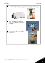
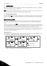
background image

vacon  nx

ac drives

optc2/c8 

modbus/n2 option board

user manual

Summary of Contents for NX OPTC2

Page 1: ...vacon nx ac drives optc2 c8 modbus n2 option board user manual ...

Page 2: ... 16 6 MODBUS 19 6 1 Modbus RTU protocol introduction 19 6 1 1 Supported functions 21 6 1 2 Exception responses 23 6 2 Modbus interface 25 6 2 1 Modbus registers 25 6 2 2 Process data 25 6 2 3 Process data in 26 6 2 4 Process data out 27 6 2 5 Parameters 30 6 2 6 Actual values 30 6 2 7 Example messages 31 6 3 Start up test 33 7 METASYS N2 34 7 1 Metasys N2 Protocol Introduction 34 7 2 Metasys N2 in...

Page 3: ...fieldbus board The con verter can then be controlled monitored and programmed from the host system If you purchase your RS 485 Option Board separately please note that it shall be installed in slot E on the control board of the frequency converter WARNING Internal components and circuit boards are at high potential when the frequency converter is connected to the power source This voltage is extre...

Page 4: ...DC Communications Modbus RTU Metasys N2 As described in document Modicon Modbus Protocol Reference Guide Find it for example at http public modicon com As described in Metasys N2 System Protocol Specifica tion Baud rate 300 600 1200 2400 4800 9600 19200 and 38400 kbaud Addresses 1 to 247 Environment Ambient operating temperature 10 C 55 C Storing tempera ture 40 C 60 C Humidity 95 no condensation ...

Page 5: ...of the frequency converter takes place through the stan dard Vacon Interface Board Connector 3 1 RS 485 OPTC2 option board Figure 1 Vacon RS 485 option board OPTC2 Signal Connector Description NC 1 No connection VP 2 Supply voltage plus 5V RxD TxD N 3 Receive Transmit data A RxD TxD P 4 Receive Transmit data B DGND 5 Data ground reference potential for VP You can use this pin 1 to bypass the cable...

Page 6: ... option board OPTC8 Signal Connector Description Shield 1 Cable shield RxD TxD N 3 Receive A DGND 5 Data ground reference potential for VP VP 6 Supply voltage plus 5V RxD TxD P 8 Receive Transmit data B Table 3 OPTC8 bus connector signals X4 X1 Bus connector Jumpers Interface board connector Grounding plate 1 2 3 4 5 9 8 7 6 ...

Page 7: ... the whole board for the grounding of the bus cable shield Just detach the terminal block 1 Strip about 5 cm of the cable and cut off the grey cable shield Remember to do this for both bus cables except for the last device See pictures below 2 Leave no more than 1 cm of the cable outside the terminal block and strip the data cables at about 0 5 cm to fit in the terminals See pictures below Note Do...

Page 8: ...8 vacon layout and connections Tel 358 0 201 2121 Fax 358 0 201 212 205 3 Figure 5 ...

Page 9: ...ass the shield We recommend you to use an Abico connector to fit the shields into the terminal 1 Strip about 5 cm of the cable and cut off the grey cable shield Remember to do this for both bus cables except for the last device 2 Leave no more than 1 cm of the cable outside the terminal block and strip the data cables at about 0 5 cm to fit in the terminals See Figure 6 Note Do this for both bus c...

Page 10: ...r X1 on the OPTC8 is used for grounding selection If position ON is selected it means that the D sub connector PIN1 is connected directly to ground Selection of position OFF means that PIN1 is connected to ground via an RC filter Jumper X1 has no effect on OPTC2 Figure 8 Grounding jumper X1 X4 X1 ON OFF 1 2 3 4 5 9 8 7 6 ...

Page 11: ...3 3 4 Bus terminal resistors If Vacon is the last device of the fieldbus line the bus termination must be set Use jumper X4 ON po sition or external termination resistors e g in DSUB 9 connector See Figure 9 Figure 9 Using jumper X4 to set the bus termination X4 X1 1 2 3 4 5 9 8 7 6 ON OFF ...

Page 12: ...5 bus state should be neather 0 200 7V or 0 200 7V Illegal bus state is 200mV 200mV Number of nodes Bias resistance 2 5 1 8 kohm 5 10 2 7 kohm 11 20 12 kohm 21 30 18 kohm 31 40 27 kohm Table 4 Bias resistor size vs number of node Fail safe biasing in OPTC2 option board Connect resistor biasing resistors between pins 2 and 4 as well as pins 3 and 5 as shown in pic ture Matters related to this are d...

Page 13: ...oard is activated and in RUN state Option board is ready for external communication Blinking slow once 5 secs Option board is activated and in FAULT state Internal fault of option board Fieldbus status LED FS GREEN LED is Meaning OFF Fieldbus module is waiting for parameters from the fre quency converter No external communication ON Fieldbus module is activated Parameters received and module activ...

Page 14: ...14 vacon installation Tel 358 0 201 2121 Fax 358 0 201 212 205 4 4 INSTALLATION OF VACON NX RS 485 BOARD A Vacon NX frequency converter B Remove the cable cover C Open the cover of the control unit ...

Page 15: ...on board in slot E on the control board of the frequency con verter Make sure that the grounding plate see below fits tightly in the clamp E Make a sufficiently wide opening for your cable by cutting the grid as wide as necessary F Close the cover of the control unit and the cable cover X4 X1 1 2 3 4 5 ...

Page 16: ...ed with the expander board Enter the following menu level G with the Menu button right At this level you can browse through slots A to E with the Browser buttons to see what expander boards are connected On the lowermost line of the display you also see the number of parameter groups associated with the board If you still press the Menu button right once you will reach the parameter group level wh...

Page 17: ...nication timeout below 6 OPERATE MODE 1 1 Normal Reserved for later use Table 5 RS 485 parameters The parameters of every device must be set before connecting to the bus Especially the parameters Communication Protocol Slave Address and Baud Rate must be the same as in the master configura tion Communication timeout The RS 485 board initiates a communication error if communication is broken for as...

Page 18: ...58 0 201 2121 Fax 358 0 201 212 205 5 Good messages 0 999 Number of messages received without communication errors Error messages 0 64 Number of messages received with CRC or parity errors Table 6 RS 485 message indications ...

Page 19: ...o queries that are addressed to them individually Responses are not returned to broadcast queries from the master A transaction comprises a single query and single response frame or a single broadcast frame The transaction frames are defined below Master s message Slave response START START ADDRESS ADDRESS FUNCTION FUNCTION DATA DATA CRC CRC END END Figure 13 The basic structure of a Modbus frame ...

Page 20: ...cimal digits in the range of 00 to FF hexadeci mal These can be made from a pair of ASCII characters or from one RTU character according to the network s serial transmission mode The data field of messages sent from a master to slave devices contains additional information which the slave must use to take the action defined by the function code This can include items like discrete and register add...

Page 21: ...DATA Starting ddress HI 07 hex Starting address 07d0 hex 2000 Starting address LO D0 hex No of points HI 00 hex Number of registers 0003 hex 3 No of points LO 03 hex ERROR CHECK CRC HI 05 hex CRC field 0546 hex 1350 CRC LO 46 hex 6 1 1 2 Read Input Registers The query message specifies the starting register and the quantity of registers to be read Registers are addressed starting with zero i e reg...

Page 22: ...fies the register references to be preset Registers are addressed starting with zero i e register 1 is addressed as 0 Example of a request to preset two registers starting at 42001 to 0001hex and 0010hex in Slave device 1 ADDRESS 01 hex Slave address 1 hex 1 FUNCTION 10 hex Function 10 hex 16 DATA Starting ddress HI 07 hex Starting address 07d0 hex 2000 Starting address LO D0 hex No of registers H...

Page 23: ...LEGAL DATA VALUE The received data value is not an allowable value for the slave 06 SLAVE DEVICE BUSY The message was received without error but the slave was engaged in processing a long duration program command Table 8 Exception response codes Example of an exception response In an exception response the Slave sets the most significant bit MSB of the function code to 1 The Slave returns an excep...

Page 24: ...eption response Answer Slave Master ADDRESS 01 hex Slave address 1 hex 1 FUNCTION 14 hex Most significant bit set to 1 ERROR CODE 02 hex Error code 02 Illegal Data Address ERROR CHECK CRC HI AE hex CRC field AEC1 hex 44737 CRC LO C1 hex Reply frame 01 14 02 AE C1 ...

Page 25: ... mapped to drive ID s as follows ID Modbus register Group R W 1 98 40001 40098 30001 30098 Actual Values 30 1 99 40099 30099 Fault Code 30 1 101 1999 40101 41999 30101 31999 Parameters 30 1 2001 2099 42001 42099 32001 32099 Process Data In 20 20 2101 2199 42101 42199 32101 32199 Process Data Out 20 20 Table 9 Index table 6 2 2 Process data The process data fields are used to control the drive e g ...

Page 26: ...eed is set with Refer ence REF With PD1 PD8 the device can be given other reference values e g Torque reference With the StatusWord SW read by the Master the status of the device can be seen Actual Value ACT and PD1 PD8 show the other actual values 6 2 3 Process data in This register range is reserved for the control of the frequency converter Process data in is located in range ID 2001 2099 The r...

Page 27: ...between the set minimum and maximum frequencies 6 2 3 3 Process data in 1 to 8 Process Data In values 1 to 8 can be used in applications for various purposes Update rate is 10 ms for all values See Vacon NX Application Manual for usage of these data values 6 2 4 Process data out This register range is normally used to fast monitoring of the frequency converter Process data out is located in range ...

Page 28: ...Warning 5 Ref frequency not reached Ref Frequency reached 6 Motor is running at zero speed 7 Flux Not Ready Flux Ready 8 TC Speed Limit Active TC Speed Limit Not Active 9 Detected Encoder Direction Clockwise Encoder Direction Counterclockwise 10 UV Fast Stop Active UV Fast Stop Not Active 11 15 Not In use Not In use Table 15 Status word bit descriptions 6 2 4 2 General status word 15 14 13 12 11 1...

Page 29: ... converter Used normally as Speed reference The allowed scaling is 10000 10000 In the application the value is scaled in percentage of the fre quency area between set minimum and maximum frequency 6 2 4 4 Process data out 1 to 8 Process Data Out values 1 to 8 can be used in application for various purposes Update rate is 10ms for all values See APPENDIX 1 for usage of these values ...

Page 30: ...ead Holding Registers 30101 31999 101 1999 04 Read Input Registers 40101 41999 101 1999 06 Preset Single Register 40101 41999 101 1999 16 Preset Multiple Registers 40101 41999 101 1999 Table 17 Parameters 6 2 6 Actual values The actual values as well as parameter addresses are determined in the application Every actual value has been given an ID number in the application The ID numbering of the ac...

Page 31: ...word run bit to 1 Data LO 01 hex Data HI 00 hex Data 2 0000 hex 0 General con trol word 0 Data LO 00 hex Data HI 13 hex Data 3 1388 hex 5000 Speed Reference to 50 00 Data LO 88 hex ERROR CHECK CRC HI C8 hex CRC field C8CB hex 51403 CRC LO CB hex Message frame 01 10 07 D0 00 03 06 00 01 00 00 13 88 C8 CB The reply to Preset Multiple Registers message is the echo of 6 first bytes Answer Slave Master...

Page 32: ... registers LO 02 hex ERROR CHECK CRC HI 93 hex CRC field B321 hex 45857 CRC LO A5 hex Message frame 01 04 08 36 00 02 93 A5 The reply to the Read Input Registers message contains the values of the read registers Answer Slave Master ADDRESS 01 hex Slave address 1 hex 1 FUNCTION 04 hex Function 4 hex 4 DATA Byte count 02 hex Byte count 4 hex 4 Data HI 13 hex Speed reference 1388 hex 5000 50 00 Data ...

Page 33: ...r 7 3 3 Master software 1 Set FB Control Word MBaddr 42001 value to 1hex 2 Frequency converter status is RUN 3 Set FB Speed Reference MBaddr 42003 value to 5000 50 00 4 The Actual value is 5000 and the frequency converter output frequency is 25 00 Hz 5 Set FB Control Word MBaddr 42001 value to 0hex 6 Frequency converter status is STOP If FB Status Word Addr 42101 bit 3 1 Status of frequency conver...

Page 34: ...rting based on high and low warning limits Support Change of State COS reporting based on high and low alarm limits Support Change of State COS reporting based on override status Always considered reliable and never out of range Writing of alarm and warning limit values beyond the range that can be held by the drive s in ternal variable will result in having that limit replaced by the Invalid Floa...

Page 35: ...the value on the keypad The value is non volatile and will remain in ef fect when the drive is turned off and back on It also remains at this value when the N2 net work releases the point The N2 system always reads the current parameter value Note On some N2 systems the system will not poll the AO point when it is being overridden In this case the N2 system will not notice a change in value if the...

Page 36: ... Operating Hours trip Hour 0 decimal AI 13 Kilowatt Hours trip kWh Trip Counter AI 14 Torque Reference 1 1 decimal AI 15 Motor Temperature Rise1 1 decimal AI 16 FBProcessDataOut1 2 32768 to 32767 0 decimal AI 17 FBProcessDataOut2 2 32768 to 32767 0 decimal AI 18 FBProcessDataOut3 2 32768 to 32767 0 decimal AI 19 FBProcessDataOut4 2 32768 to 32767 0 decimal AI 20 FBProcessDataOut5 2 32768 to 32767 ...

Page 37: ...3 General 5 3 0 1 BI 14 General 6 3 0 1 BI 15 General 7 3 0 1 Table 20 3 These binary inputs are application specific They are read from the drives General Status Word 7 3 3 Analogue Outputs AO NPT NPA Description Units Note AO 1 Comms Speed 2 decimals AO 2 Current Limit A 2 decimals AO 3 Minimum Speed Hz 2 decimals AO 4 Maximum Speed Hz 2 decimals AO 5 Accel Time s 1 decimal AO 6 Decel Time s 1 d...

Page 38: ...ntrolWord Bit_5 5 BO 7 FBFixedControlWord Bit_6 5 BO 8 FBFixedControlWord Bit_7 5 BO 9 FBFixedControlWord Bit_8 5 BO 10 FBFixedControlWord Bit_9 5 BO 11 FBFixedControlWord Bit_10 5 BO 12 FBFixedControlWord Bit_11 5 BO 13 FBFixedControlWord Bit_12 5 BO 14 FBFixedControlWord Bit_13 5 BO 15 FBFixedControlWord Bit_14 5 BO 16 FBFixedControlWord Bit_15 5 Table 22 5 These Binary Outputs are application s...

Page 39: ...fault The data connection between the Modbus N2 Master and the RS 485 option board is broken Check the installation If installation is correct contact the nearest Vacon distributor 54 Slot fault Defective option board or slot Check the board and slot Contact the nearest Vacon distributor Table 24 RS 485 option board faults You can define with parameters how the frequency converter shall react to c...

Page 40: ...ocess data OUT 6 Motor Voltage V 0 1 V 2110 Process data OUT 7 DC link voltage V 1 V 2111 Process data OUT 8 Active Fault Code Table 26 Process data OUT variables The Multipurpose Control application has a selector parameter for every Process Data The monitor ing values and drive parameters can be selected using the ID number see NX All in One Application Manual Tables for monitoring values and pa...

Page 41: ...e 0 1 2005 Process Data IN2 Free Analogia INPUT 0 01 2006 2011 PD3 PD8 Not Used Table 28 PID control and Pump and fan control applications ID Data Value Unit Scale 2003 Reference Speed Reference 0 01 2001 ControlWord Start Stop Command Fault reset Command 2004 Process Data IN1 Reference for PID controller 0 01 2005 Process Data IN2 Actual Value 1 to PID controller 0 01 2006 Process Data IN3 Actual...

Page 42: ...ID Rev A Manual authoring documentation vacon com Vacon Plc Runsorintie 7 65380 Vaasa Finland Subject to change without prior notice 2012 Vacon Plc Find your nearest Vacon office on the Internet at www vacon com ...

Reviews: