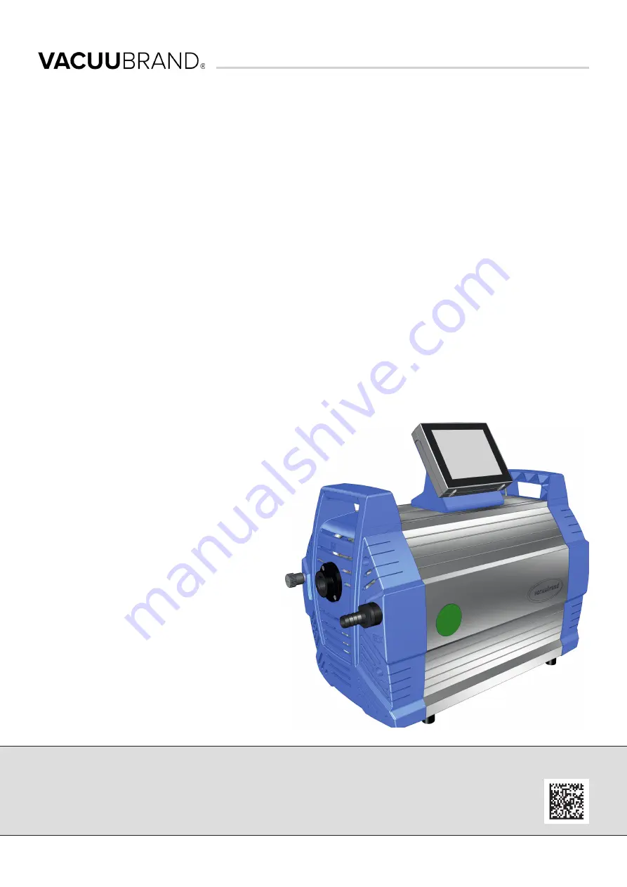
vacuubrand MD 12C NT VARIO o.C., Instructions For Use Manual
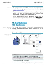
The vacuubrand MD 12C NT VARIO o.C. is a powerful and reliable vacuum pump designed for a variety of laboratory applications. For detailed operating instructions and information, download the free Instructions For Use Manual from 88.208.23.73:8080. This essential manual will help you get the most out of your vacuum pump.
Share
Download


Reviews:
No comments
Related manuals for MD 12C NT VARIO o.C.

GAUS-315EQTA
Brand: Sanden Pages: 26

130
Brand: SAHP Pages: 41

PX Series
Brand: X-POWER Pages: 44

57 Series
Brand: Zoeller Pages: 12

1552
Brand: Zip Pages: 12

CF10
Brand: Balcrank Pages: 18

ATO One for RO
Brand: Kamoer Pages: 2

GCV11SO 15047
Brand: TESY Pages: 176

CDT 30
Brand: Dantherm Pages: 17

Medana CH1-LC
Brand: Wilo Pages: 132

WSW1-80L-WM
Brand: Winston Pages: 28

GD-2250T
Brand: Gardner Denver Pages: 47

WF402
Brand: Malibu Boats Pages: 2

PK15
Brand: Barnant Company Pages: 13

DETA 0040
Brand: POBEL Pages: 9

P2 AMEX Series
Brand: Buhler Pages: 48

THJF60
Brand: York Pages: 16

cascade 450
Brand: Hozelock Pages: 2


