background image

TouchVIEW

433 MHz Wireless Positioning System

The Vaddio TouchVIEW transmits positioning requests through the air instead of

hard wires, allowing greater flexibiliby.  Position switches can now be used in any

location without running cable from the switches to Vaddio’s ControlVIEW

.  The

wireless connection can extend over 100 feet.

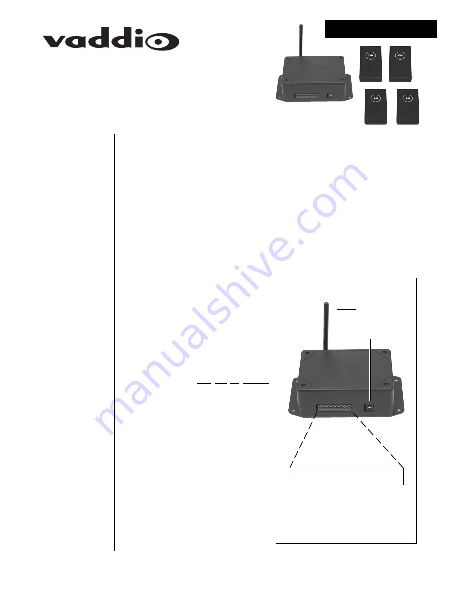
• Carefully remove the device and parts from the packing material.

• Set the unit on a flat, solid surface.  Unpack and identifiy the following parts:

– Four, single-position transmitters

– One, receiver

– One, eight contact female 5mm terminal block

– One, power supply

Introduction

Setting Up

Your

TouchVIEW

1

Unpacking

Your

TouchVIEW

TouchVIEW Receiver (see Figure 1)

The receiver ouputs are connected to

Vaddio’s ControlVIEW or ControlVIEW

Expander inputs.

• Using the terminal block, attach wires

from button outputs 

one

 through 

four

 to

the preset inputs on the back of the

ControlVIEW.

– Only one wire per connection,

connections 

can not be shared

with an input from another source

on the ControlVIEW.

– The outputs can be connected

to any one of the twelve inputs on

the ControlVIEW.

• Attach a wire from the ground (GND)

connection on the receiver to a ground

connection on the ControlVIEW.

• Plug the power supply into the receiver.

• Plug the other end of the power supply

into a power outlet.

Figure 1 – TouchVIEW Receiver.

OUTPUT 1

OUTPUT 2

OUTPUT 3

OUTPUT 4

NONE

NONE

NONE

GROUND

• • • • • • • •

12 VDC POWER

ANTENNA

Installation & User Guide

Summary of Contents for TouchVIEW

Page 1: ... TouchVIEW 1 Unpacking Your TouchVIEW TouchVIEW Receiver see Figure 1 The receiver ouputs are connected to Vaddio s ControlVIEW or ControlVIEW Expander inputs Using the terminal block attach wires from button outputs one through four to the preset inputs on the back of the ControlVIEW Only one wire per connection connections can not be shared with an input from another source on the ControlVIEW Th...

Page 2: ...on the receiver and all four of the transmitters Receiver Setting the Address 1 Using a small Phillips screwdriver remove the four screws on the top of the receiver 2 Carefully pull the top cover off the re ceiver 3 Locate the RED DIP Switches 1 8 When shipped all of the switches will be in the OFF position 4 Set the switches to the same address as the transmitter remember this address 5 Carefully...

Page 3: ..._____ __________________________________________________________________ __________________________________________________________________ __________________________________________________________________ __________________________________________________________________ __________________________________________________________________ ___________________________________________________________...

Page 4: ...product s has been disas sembled or damaged through misuse accident modifications or unauthorized repair Shipping and Handling Vaddio will not pay for inbound shipping transportation or insurance charges or accept any responsibility for loss and or damage from inbound transit Vaddio requires that all overseas returns are shipped via UPS Vaddio will pay for outbound shipping transportation and insu...

Reviews: