
Summary of Contents for VRT 350f
Page 4: ...Contents 4 Installation instructions VRT 350f 0020131978_00 12 Customer service 32...
Page 33: ......
Page 34: ......
Page 35: ......
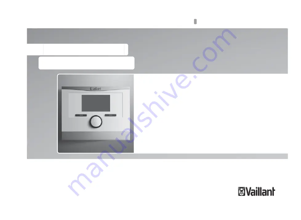
The Vaillant VRT 350f Operating Instructions Manual is a comprehensive and essential guide for users of this top-of-the-line thermostat. Easily download this manual for free from our website, ensuring that you can optimize the functionality of your Vaillant VRT 350f and enjoy its advanced features effortlessly.
Page 4: ...Contents 4 Installation instructions VRT 350f 0020131978_00 12 Customer service 32...
Page 33: ......
Page 34: ......
Page 35: ......


