
H5 S
ERIES
DV ZC Gas Fireplace
1100IN (NG) & 1100IP (LPG)
1150ILN (NG) & 1150ILP (LPG)
4003682-06
©2016, Miles Industries Ltd.
Ce guide est disponible en français sur demande.
This appliance is only for use with the type
of gas indicated on the rating plate. This
appliance is not convertible for use with
other gases, unless a certi
fi
ed kit is used.
This appliance is a domestic room-heating
appliance. It must not be used for any other
purposes such as drying clothes, etc.
This appliance is suitable for installation in a
bedroom or bed sitting room.
This appliance may be installed in an
after-market permanently located,
manufactured (mobile) home where not
prohibited by local codes.
INSTALLER
Leave this manual
with the appliance.
CONSUMER
Retain this manual
for future reference.
Please read this manual
BEFORE installing and
operating this appliance.
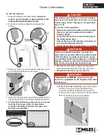
This manual contains instructions to install the
ENGINE ONLY.
A trim kit is
REQUIRED
to
complete the installation. A barrier screen is
provided with the trim kit.
Refer to the manual
supplied with the trim for installation.
HOT GLASS
WILL
CAUSE BURNS.
DO NOT TOUCH
GLASS
UNTIL COOLED.
NEVER
ALLOW CHILDREN
TO TOUCH GLASS.
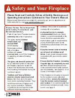
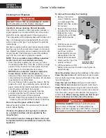
DANGER
!
A barrier designed to reduce the risk of burns from the hot
viewing glass is provided with this appliance and shall be
installed for the protection of children and other at-risk
individuals.
Installation & Owner’s Manual
— Do not store or use gasoline or other
fl
ammable vapors and liquids in the
vicinity of this or any other appliance.
— WHAT TO DO IF YOU SMELL GAS
▪
Do not try to light any appliance.
▪
Do not touch any electrical switch; do
not use any phone in your building.
▪
Leave the building immediately.
▪
Immediately call your gas supplier from
a neighbor’s phone. Follow the gas
supplier’s instructions.
▪
If you cannot reach your gas supplier,
call the
fi
re department.
— Installation and service must be
performed by a quali
fi
ed installer, service
agency or the gas supplier.
!
WARNING
FIRE OR EXPLOSION HAZARD
Failure to follow safety warnings exactly
could result in serious injury, death, or
property damage.


