background image

Summary of Contents for 502CP

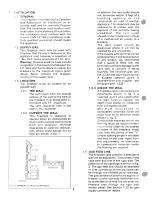
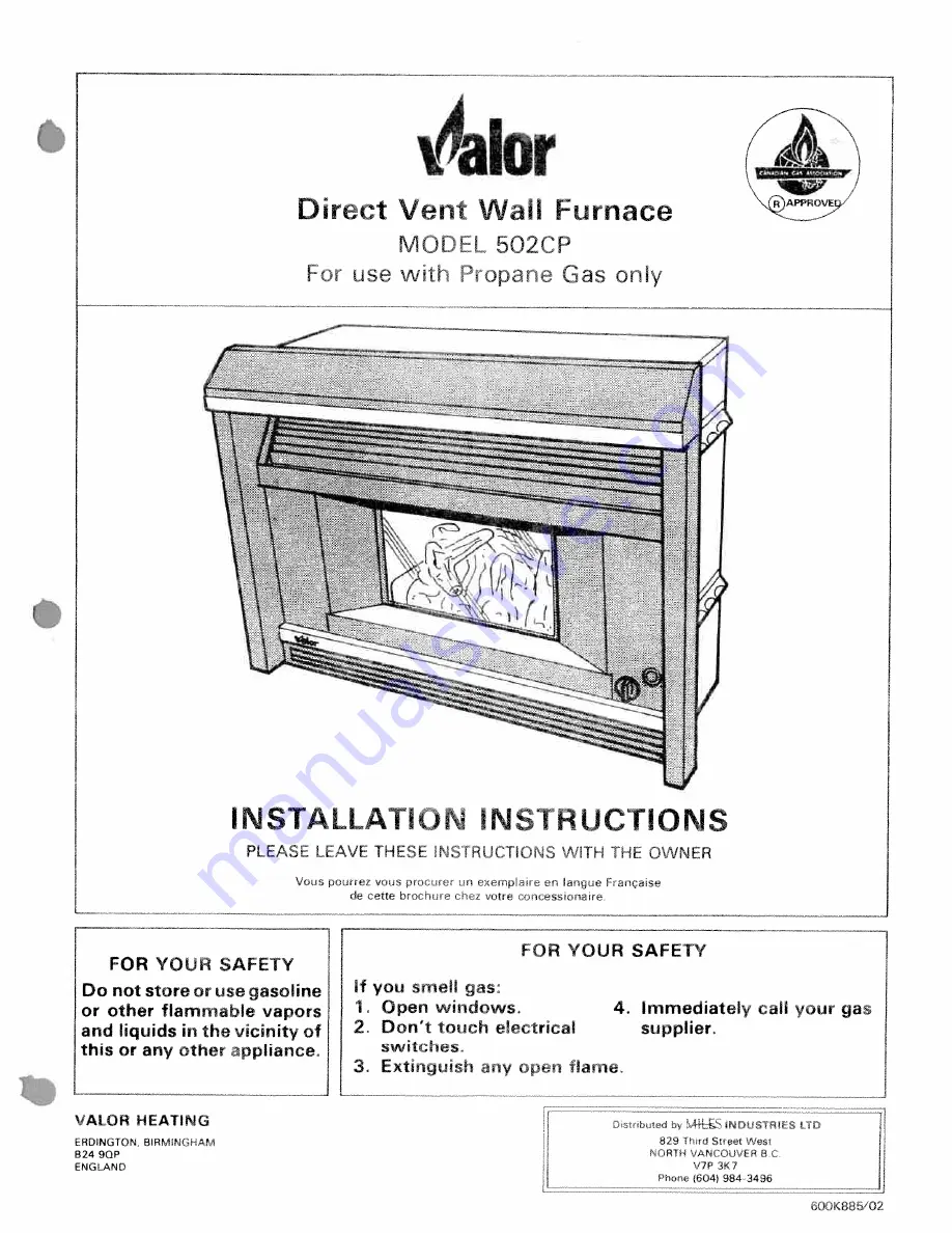
Page 1: ...TIONS PLEASE LEAVE THESE NS1RJCTlONS WiTH THE OWNER Vcds poJrrez vos p n earnp r larrgue Fançase de cette brocrrrn r z votre olcesson ore FOR YOUR SAFETY FOR YOUR SAFETY Do not store or use gasoline or other flammable vapors and liquids in the vicinity of this or any other appliance If you smell gas 1 Open windows 4 Immediately call your gas 2 Don t touch electrical supplier switches 3 Extmguish a...

Page 2: ...minate within 6 feet of a mechanical air supply to a building The vent outlet should be positioned where it will not be covered by any snowdrifts If the outside vent terminal is to be located where it will be accessible to any person we recommend that a guard is fitted over the terminal to prevent damage to the vent and to prevent it being touched The terminal gets very hot in use and could cause ...

Page 3: ... ILL JILL I 4 6Max Mantle j4 GAS LINE ACCESS 12 OPENINGS FIG 2 FRAMING CEILING 36 Mir 4 11 2 111 2 4 CENTER LINE OF FIREPLACE 36 Mm p F 13 16 Y 1 7 7 7 7 7 7 7 7 7 7 7 7 7 7 FINISHED HEARTH LEVEL BACK OF FIREPLACE HG 3 CLEARANCES fO COMBUSTIBLE MATERIALS GAS LINE AREAS 2 ...

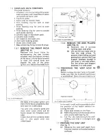
Page 4: ...most other loose Items will be found inside the fireplace outer case Check that all the contents listed are in the pack and are undamaged 3 1 5 2 REMOVE THE SIDE PILLARS SEE FIG 5 a Remove the 3 screws holding each side pillar b Lift up the top cross unit to free the side pillars To prevent them falling out and getting lost remove the 2 top support brackets located in the slots in the side pillars...

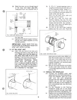
Page 5: ... one of the vent tube locating plates over the vent unit Push the plate uptothe outer case Make sure that the ceramic seals are located in the well in the plate and up to the firebox back and that they are not trapped between the locating plate and the outer case e Secure the locating plate to the back of the outer case using the seven 8 thread tapping screws provided see fig 9 1 9 INSTALL THE FIR...

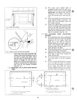
Page 6: ... FIT OUTSIDE VENT LOCATION PLATES a Fit a wall plate over the outside wall end of the vent unit with the dished projection to the inside Push the plate up to the wall so that the dished projection locates inside the outer vent shield tube Mark the location plate fixing holes on the wall Remove the plate b Drill the fixing holes in the wall and insert wall plugs if necessary c Replace the location ...

Page 7: ... These openings are covered by metal plates Remove the cover plate from the chosen access opening by unfastening the fixing screws Cut out sufficient of the cover plate to allow the feed line to pass through it Do not cut away more than is necessary Refit the cover plate after cutting in order that heat losses through the back of the fireplace are minimised All gas piping and connections must be t...

Page 8: ...ilot lights If the pilot does not ignite after ensuring that all air has been purged from the gas lines check that the electrode gap is set as shown in fig 16 d Hold the control knob in for a further 10 seconds to prevent the flame failure detector from shutting off the gas while its thermocouple probe is warming up The pilot should then remain lit e Check the pilot flame See figs 1 7a 1 7b f Turn...

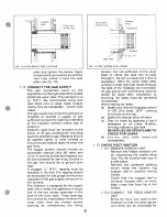
Page 9: ...rear of the log into recess D in the support bed C Place Log 4 3 at the right side of the support bed Locate the hole at the front edge onto tab E of the front support rail Locate the underside of the log onto the recess G in the support bed The Logs should now be as shown in fig 19 d Place Log 4 between Logs 4 2 4 3 Locate the groove situated under the front edge of the log onto tab F on the fron...

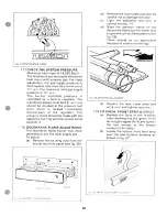
Page 10: ...ourners are as in the table belowand that the appearance of the flames is correct See figs 23 24 Turn off by pushing in the knob s ightly and turning clockwise until the OFF marking is at the top Control Main Decorative Position Burner Burner 1 IGN Off Off Pilot ignition position 2 Low Off Center area only_on 3 Low Center area Center area only on only_on 4 High All areas All areas on on HG 23b WRO...

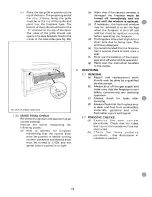
Page 11: ... The decorative flame burner may need adjusting to suit the local supply gas To adjust a Remove the six wing nuts from the burner box front panel see fig 25 b Remove the cover plate and seal Be careful not to damage the seal c Light the appliance and turn to control setting 4 d Slide the aeration sleeve on the decorative flame burner either way to give the correct flame pattern s e fig 26 There sh...

Page 12: ...dow may be removed to re set the logs when the fireplace is shut off and cold but must be replaced ecurely before operating the fireplace d The fireplace may smell siightlyfora short time due to being new This will soon disappear e It is recommended that the fireplace has a service check at least once a year f Point out the location of the supply pipe shut off valve and its operation g Hand over t...

Reviews: