background image

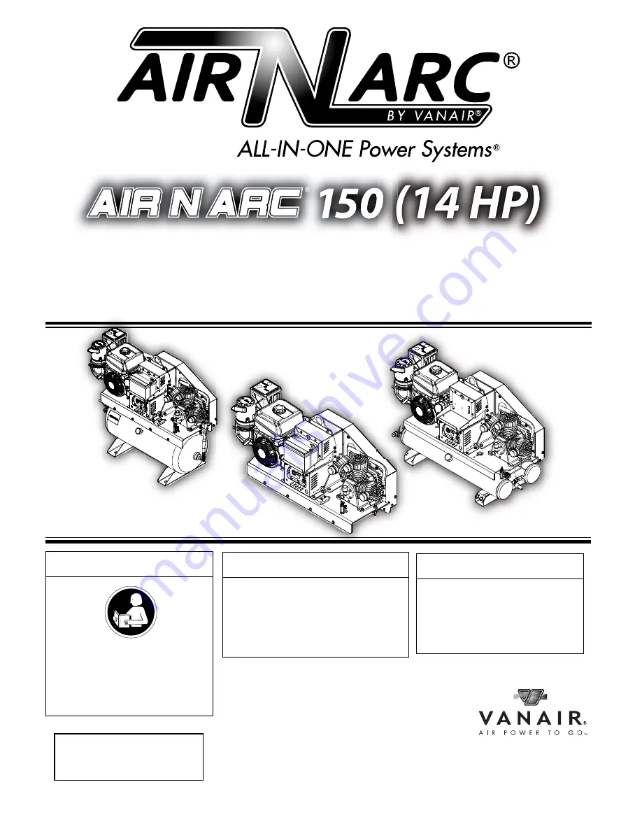
ALL-IN-ONE POWER SYSTEMS

®

WELDER • GENERATOR • AIR COMPRESSOR • BATTERY BOOSTER

OPERATION MANUAL & PARTS LIST

©2014 Vanair Manufacturing, Inc.

All rights reserved

090051-OP_r0

Effective Date:

2-2014

NOTE

Read this manual before installing, 

operating or servicing this 

equipment. Failure to comply with 

the operation and maintenance 

instructions in this manual WILL 

VOID THE EQUIPMENT WARRANTY.

NOTE

Use only Genuine Vanair Parts. 

Inspect and replace damaged 

components before operation. 

Substituting non-Vanair 

components WILL VOID THE 
COMPRESSOR WARRANTY! 

Vanair Manufacturing, Inc.

10896 West 300 North

Michigan City, IN 46360

Phone: (219) 879-5100

            (800) 526-8817

Service Fax: (219) 879-5335

Parts Fax: (219) 879-5340

Sales Fax: (219) 879-5800

www.vanair.com

NOTE

Making unauthorized modifications to 

the system components WILL VOID THE 

WARRANTY!

Always inform Vanair Manufacturing, 

Inc. before beginning any changes to the 

Air N Arc system.

KEEP THE MANUAL

WITH THE VEHICLE

Summary of Contents for AIR N ARC CONTRACTOR 150 Series

Page 1: ...T WARRANTY NOTE Use only Genuine Vanair Parts Inspect and replace damaged components before operation Substituting non Vanair components WILL VOID THE COMPRESSOR WARRANTY Vanair Manufacturing Inc 10896 West 300 North Michigan City IN 46360 Phone 219 879 5100 800 526 8817 Service Fax 219 879 5335 Parts Fax 219 879 5340 Sales Fax 219 879 5800 www vanair com NOTE Making unauthorized modifications to ...

Page 2: ...rcial industrial users and persons trained and experienced in the use and maintenance of industrial equipment In the event of a warranty claim covered by this Limited Warranty the exclusive remedies shall be at Vanair s sole discretion i repair or ii replacement iii where authorized in writing by Vanair in appropriate cases the reasonable cost of repair or replacement at an authorized Vanair servi...

Page 3: ... 4 4 ENCLOSED SPACES CAN CAUSE A BUILD UP OF NOXIOUS FUMES AND OVERHEATING 3 1 4 5 ARC RAYS CAN BURN EYES AND SKIN 3 1 4 6 WELDING CAN CAUSE FIRE AND EXPLOSION 3 1 4 7 FLYING METAL CAN INJURE EYES 4 1 4 8 HOT PARTS CAN CAUSE SEVERE BURNS 4 1 4 9 NOISE CAN DAMAGE HEARING 4 1 4 10 MAGNETIC FIELDS CAN AFFECT PACEMAKERS 4 1 4 11 CYLINDERS CAN EXPLODE IF DAMAGED 4 1 5 ENGINE HAZARDS 5 1 5 1 BATTERY EXP...

Page 4: ...BOLS FOR INSTALLATION OPERATION AND MAINTENANCE 7 1 7 1 FALLING UNIT CAN CAUSE INJURY 7 1 7 2 OVERHEATING CAN DAMAGE MOTORS 7 1 7 3 FLYING SPARKS CAN CAUSE INJURY 7 1 7 4 OVERUSE CAN CAUSE OVERHEATING 8 1 7 5 ENCLOSED SPACES CAN CAUSE A BUILD UP OF NOXIOUS FUMES AND OVERHEATING 8 1 7 6 TILTING OF TRAILER CAN CAUSE INJURY 8 1 7 7 READ INSTRUCTIONS 8 1 7 8 H F RADIATION CAN CAUSE INTERFERENCE 8 1 7 ...

Page 5: ... SCHEDULE TABLE 26 5 4 REPLACEMENT PARTS 31 5 5 PARTS REPLACEMENT AND ADJUSTMENT PROCEDURES 31 5 5 1 ADJUSTING THE ENGINE SPEED 32 5 5 2 REPLACING AND RE TENSIONING THE COMPRESSOR AND OR GENERATOR DRIVE BELTS 32 5 5 2 1 ACCESSING THE DRIVE BELTS REMOVING THE BELT GUARD SHIELD 32 5 5 2 2 REPLACING THE BELT GUARD SHIELD 32 5 5 2 3 RE TENSIONING THE AIR COMPRESSOR DRIVE BELT 32 5 5 2 4 COMPRESSOR BEL...

Page 6: ... ALL 30 GALLON MODEL OPTIONS 56 7 3C FRAME ASSEMBLY ALL SKID MOUNT MODEL OPTIONS 56 7 4 ENGINE AND DRIVE PARTS 1 OF 2 58 7 4 ENGINE AND DRIVE PARTS 2 OF 2 60 7 5 BELT GUARD ASSEMBLY 62 7 6 ELECTRICAL SYSTEM 64 7 7 CONTROL ASSEMBLY 30 GALLON AND SKID MOUNT REMOTE OPTIONS 68 7 8A AIR TANK ALL 10 GALLON MODEL OPTIONS 70 7 8B AIR TANK ALL 30 GALLON MODEL OPTIONS 72 7 9 DECAL LOCATIONS 74 7 10 WIRING D...

Page 7: ...readings and also the number of operational hours available if applicable Note that the above information will also need to be included on the Return Material Authorization Form per Step 6 this form is necessary for warranty processing if the warranty claim is deemed valid by the service case review 3 Contact the Vanair Service Department by phone 1 219 879 5100 to speak with a Service Technician ...

Page 8: ...0 526 8817 260940 MODEL NUMBER SERIAL NUMBER MAXIMUM PRE SSURE COMPRE SSOR INPUT RPM www vanai r com C B A KOHLER MODEL NO XXXXX SERIAL NO XXXXX S N XXXXX KEY DESCRIPTION KEY DESCRIPTION A ENGINE SERIAL NUMER TAG C MACHINE SERIAL PLATE SERIAL NUMBER B COMPRESSOR SERIAL NUMBER TAG Figure W 1 Machine Serial Number Location ...

Page 9: ... returned freight collect Freight costs will be addressed at the time the claim is closed The customer pays any additional costs for warranty parts delivered through expedited services i e Next Day Second Day VANAIR WILL NEVER ACCEPT ANY INVOICES FOR PARTS RETURNED ANY PARTS RETURNED VIA INVOICE WILL BE RETURNED FREIGHT COLLECT NO PARTS ARE TO BE RETURNED FREIGHT COLLECT Vanair Mfg Inc strives to ...

Page 10: ...PAGE VIII 090051 OP_r0 FEB 2014 BLANK PAGE Vanair Manufacturing Inc vanair com 800 526 8817 ...

Page 11: ... extremely careful attention and follow the given instructions or indications to avoid any possible hazard 1 4 ARC WELDING HAZARDS 1 4 1 ELECTRICAL SHOCK CAN KILL Touching live electrical parts can cause fatal shocks or severe burns The electrode and work circuit are electrically live whenever the output is on The input IMPORTANT It is mandatory that all operators read this manual before operating...

Page 12: ... check and be sure that input power cord ground wire is properly connected to ground terminal in disconnect box or that cord plug is connected to a properly grounded receptacle outlet When making input connections attach proper grounding conductor first and double check connections Frequently inspect input power cord for damage or bare wiring and replace cord immediately if damaged bare wiring can...

Page 13: ...NOXIOUS FUMES AND OVERHEATING Do not use in enclosed spaces where deadly exhaust gases can build up and machine can overheat causing fire 1 4 5 ARC RAYS CAN BURN EYES AND SKIN Arc rays from the welding process produce intense visible and invisible ultraviolet and infrared rays that can burn eyes and skin Sparks fly off from the weld Wear an approved welding helmet fitted with a proper shade of fil...

Page 14: ... any welding Follow requirements in OSHA1910 252 a 2 iv and NFPA 51B for hot work and have a fire watcher and extinguisher nearby 1 4 7 FLYING METAL CAN INJURE EYES Sparks and flying metal can be caused by welding chipping wire brushing and grinding As welds cool they can throw off slag Wear approved safety glasses with side shields even under your welding helmet 1 4 8 HOT PARTS CAN CAUSE SEVERE B...

Page 15: ...eld rubber gloves and protective clothing when working on a battery Stop engine before disconnecting or connecting battery cables or servicing battery Do not allow tools to cause sparks when working on a battery Do not use weld mode to charge batteries or jump start vehicles Observe correct polarity and on batteries Disconnect negative cable first and connect it last 1 5 2 FUEL CAN CAUSE FIRE OR E...

Page 16: ...losed spaces where deadly exhaust gases can build up and machine can overheat causing fire 1 5 7 BATTERY ACID CAN BURN SKIN AND EYES Do not tip battery Replace damaged battery Flush eyes and skin immediately with water 1 5 8 ENGINE HEAT CAN CAUSE FIRE Do not locate unit on over or near combustible surfaces or flammables Keep exhaust and exhaust pipes way from flammables 1 5 9 EXHAUST SPARKS CAN CA...

Page 17: ... 6 7 READ INSTRUCTIONS Read Owner s Manual before using or servicing unit Stop engine and release air pressure before servicing Use only genuine Air N Arc replacement parts 1 7 ADDITIONAL SYMBOLS FOR INSTALLATION OPERATION AND MAINTENANCE 1 7 1 FALLING UNIT CAN CAUSE INJURY Use lifting bail to lift unit and properly installed accessories only Lift and support unit only with proper equipment and co...

Page 18: ...avigation safety services computers and communications equipment Have only qualified persons familiar with electronic equipment to perform this installation The user is responsible for having a qualified electrician promptly correct any interference problem resulting from the installation If notified by the FCC about interference stop using the equipment at once Have the installation regularly che...

Page 19: ...w nfpa org and www sparky org Safe Handling of Compressed Gases in Cylinders CGA Pamphlet P 1 from Compressed Gas Association 1735 Jefferson Davis Highway Suite 1004 Arlington VA 22202 4102 phone 703 412 0900 website www cganet com Code for Safety in Welding and Cutting CSA StandardW117 2 from Canadian Standards Association Standards Sales 178 Rexdale Boulevard Rexdale Ontario Canada M9W 1R3 phone...

Page 20: ... Connect work clamp to workpiece as close to the weld as possible About Pacemakers Pacemaker wearers should consult their doctor before welding or going near welding operations If cleared by your doctor then following the above procedures is recommended 1 11 SAFETY DECALS Safety decals are placed onto or located near system components that can present a hazard to operators or service personnel All...

Page 21: ... Setting 95 125 PSI Compressor Air Filter x 3 Assemblies Pleated Paper Dry Type Oil Type Capacity Vanguard Reciprocating Oil ISO 68 or equivalent non detergent Service 1 QuartsIII Air Tank Capacity 30 Gallon Tank or Ten 10 Gallon Tank Tank Pressure Rating 200 PSI Safety Relief Valve Setting 150 PSI Electrical System 12 VDC Cooling System Air cooled Instrument Gauges Pressure Gauge Adjustable Air P...

Page 22: ...anair Manufacturing Inc vanair com 800 526 8817 TABLE 2B SPECIFICATIONS UNIT WEIGHT AND DIMENSIONS Dimensions Package Length in Width in Height in Weight lb wet Skid Mount 50 34 18 20 24 24 425 Tank Mount 30 Gallon 50 74 19 00 40 75 565 Tank Mount 10 Gallon 50 50 21 00 30 25 510 ...

Page 23: ... vanair com DANGER Grounding must consist of a minimum 4 gauge wire between the instrument panel the machine and the truck chassis DANGER DO NOT install in enclosed spaces WARNING ELECTRICAL HAZARD Be sure the battery is disconnected before starting the installation NOTE Install electrical components circuit breakers pressure switches toggle switches etc in locations where exposure to water or moi...

Page 24: ...rocedure 1 Unbolt the unit from the skid remove the mounting nuts lock washers washers and mounting bolts securing the machine to the shipping crate 2 Using a proper hoist lift and place the unit in a preliminary position on the service body of the vehicle so that access is easily attained and there is enough space surrounding the mounting area for cooling purposes 3 Leaving the unit in the prelim...

Page 25: ...AIR N ARC 150 SERIES SECTION 3 INSTALLATION 090051 OP_r0 FEB 2014 PAGE 15 Vanair Manufacturing Inc vanair com 800 526 8817 NOTES ...

Page 26: ...GENERATOR H WELD BATTERY BOOSTER CONNECTOR J COMPRESSOR SIGHT GLASS K PILOT VALVE WARM UP L COMPRESSOR UNIT M INNER STAGE TUBING N COMPRESSOR AIR FILTER S P DRIVE BELT GUARD Q LIFTING BAIL KEY DESCRIPTION R FUEL FILL PORT CAP V PRESSURE GUAGE S AIR OUT SERVICE VALVE W TANK RELIEF VALVEI T AIR RESERVIOR TANK S X CONTROL LINE CONNECTION U MOISTURE DRAIN S Y DISCHARGE LINE CONNECTION I Not shown Air ...

Page 27: ...ures detailed in this section NOTE Before starting the Air N Arc 150 Series machine read this section thoroughly and familiarize yourself with the controls and indicators their purpose location and use DANGER Grounding must consist of a minimum 4 gauge wire between the instrument panel the machine and the truck chassis WARNING Follow all applicable safety recommendations as outlined in Section 1 S...

Page 28: ...shut the engine off at any time turn the engine control switch to the OFF position A1 However this method is best reserved for emergency shutdown situations only NOTE Air compressor will start automatically with machine start up CAUTION Compressors and engines generate heat and create hot surfaces Use caution when operating and servicing equipment Some surfaces and components may be hot KEY DESCRI...

Page 29: ...led by three factors 1 The level of air pressure in the tank and the position of the pilot valve adjustment switch refer to Figure 4 3 2 The position of the welder switch on the unit control panel and the use of the welder 3 The position of the generator switch on the control panel Consult Table 4A Engine Throttle Control Function Conditions to understand how the engine speed relates to the demand...

Page 30: ... 40 190 amps Turning the Power Dial clockwise increases the amperage and turning the Power Dial counterclockwise decreases the amperage The Power Dial may be adjusted while welding OPERATING PROCEDURE 1 With the engine shut off insert the large plug on the welding lead into the welding lead receptacle 2 Insert the small 6 pin plug on the welding lead into the 6 pin receptacle referencing the pin s...

Page 31: ...Power to the welding lead will be turned off and the engine will slow to idle speed after a 30 second delay 4 5 OPERATING THE GENERATOR To operate the generator 1 Start the engine 2 Turn the Generator switch on the control panel to the ON position For general information on the power requirements of common power tools motors and extension cords check the desired power tool motor or extension cord ...

Page 32: ...d capacity of the compressor 20 CFM 100 psi will need to be taken into consideration Check the desired power tool manufacturer s specifications to ensure that the tool capacity is within range of the compressor s operating scope 4 7 EXTREME CONDITION OPERATION When operating in extreme hot or cold conditions extra attention should be given to any indications that could lead to a serious problem Ma...

Page 33: ...IGH TEMPERATURE OPERATION The standard recommendation of 10W 30 engine oil is suitable for operation in temperatures up to 110 F Extra care should be taken to keep the engine and air compressor clean and to not restrict the air flow around the unit 4 7 3 HIGH ALTITUDE OPERATION Engine horsepower will decrease by 3 5 for every 1 000 ft increase in altitude At high altitude overall unit performance ...

Page 34: ...SECTION 4 OPERATION AIR N ARC 150 SERIES PAGE 24 090051 OP_r0 FEB 2014 BLANK PAGE Vanair Manufacturing Inc vanair com 800 526 8817 ...

Page 35: ...mpressor air filters are serviced and the engine oil is changed Please take a moment to acquaint yourself with the service schedule presented in Section 5 3 Maintenance Schedule Table For assistance in obtaining routine maintenance or replacement parts consult Section 7 1 Parts Ordering Procedure and Table 7A Recommended Spare Parts List WARNING DO NOT remove caps plugs and or other components whe...

Page 36: ...100 Hours or One Year Every 200 Hours After 300 Hours After 500 Hours KEY TASK DESCRIPTION ACTION TO TAKE REFERENCE 1 Check tension of air compressor poly link drive belt Tighten belt if necessary Consult Section 5 5 2 3 for belt tightening and belt replacement procedures 2 Clean and inspect engine air filter Consult the air filter procedure Engine Operation Manual 3 Check engine fuel lines Every ...

Page 37: ...rnal parts of compressor and driver A daily visual inspection will help to prevent dirt and debris build up which can affect machine operation When cleaning external parts always wait for machine surfaces to cool down before wiping off Continued on next page 5 3 MAINTENANCE SCHEDULE WARNING Before performing maintenance Shut down machine relieve all system pressure and lock out all power as per th...

Page 38: ...ental conditions 19 Replace engine fuel filter Consult the fuel filter replacement procedure Engine Operation Manual 20 Replace engine spark plug Check at 200 hours Consult the procedure in the Engine Operation Manual on how to change the spark plugs Continued on next page 5 3 MAINTENANCE SCHEDULE WARNING Before performing maintenance Shut down machine relieve all system pressure and lock out all ...

Page 39: ...from rough noisy or worn bearings Consult Section 5 5 2 for belt tightening and belt replacement procedures 27 Inspect compressor head valves Clean the carbon from valves and head if necessary Consult Factory Service Department for assistance Continued on next page 5 3 MAINTENANCE SCHEDULE WARNING Before performing maintenance Shut down machine relieve all system pressure and lock out all power as...

Page 40: ...t all power as per the Safety Section of this manual NOTE THAT THE SYSTEM CAN BE STARTED REMOTELY Always clearly tag the start up instrumentation against accidental system start ups during maintenance INTERVALS NOTE System maintenance personnel must be familiar with all Safety regulations set forth in the Safety Section of this manual before performing maintenance on this machine BREAK IN PERIOD M...

Page 41: ...re parts are being stored for future use make certain that they are stored in proper containers that allow for protection against contamination and kept in a clean area of moderate temperature reading For information on storing the machine package for periods of non use consult Section 5 6 2 Long Term Storage WARNING Relieve pressure from the compressor system before performing maintenance on any ...

Page 42: ... the belts have been serviced the belt guard must be secured back into position before operating the machine To re secure the belt guard refer to Section 7 5 parts 1 2 and 9 and follow these instructions 1 Align the shield s holes with the holes in the frame 2 Secure the shield to the frame by placing a truss head screw through a nylon washer and hand tightening each pair until all seven 7 pairs a...

Page 43: ... belt is too loose then it will need to be resized Consult Section 5 5 2 4 to re size a poly link belt 5 5 2 4 COMPRESSOR BELT SIZING When sizing a new compressor drive belt first remove the worn belt as explained in Section 5 5 2 3 Step 3 and Step 4 Then consult Figure 5 3 and the following procedure IMPORTANT The compressor drive belt is tensioned by the number of links in the belt Never attempt...

Page 44: ...ing that the arrow indications on the belt face the same direction as the compressor pulley arrow s 5 To determine the length overlap the last two holes of one end of the belt with two tabs of the other end matching links as shown in E 6 Use a marker to place an identifying mark where the excess link begins 7 Once the belt is sized correctly the excess overlapping link s will need to be removed be...

Page 45: ...gth of the belt has been determined refer to Section 5 5 2 4 and the belt is shortened to its fitted length refer to Section 5 5 2 5 then the belt s ends are linked together to form the completed belt loop Refer to Figure 5 5 and the following procedure 1 Place tab A corner against the inside of the link hole B nearest to thumb D 2 With thumb C push on the tab s edge in the direction indicated 3 S...

Page 46: ...t and the pulley edge 3 E Hold the belt firm enough so that it does not slip from the engine pulley Move the belt to align with the compressor pulley groove as it is being rotated 2 Rotate the pulley clockwise while still holding the belt in place Figure 5 6 Compressor Drive V Belt Removal Attachment 3 2 1 Sections 5 5 2 4 through 5 5 2 6 to size and assemble the belt 2 The belt should be linked a...

Page 47: ...ERPENTINE DRIVE BELT To re tension the generator serpentine belt consult Figure 5 7 Once the generator drive belt is established onto the engine generator and idler pulleys the spring tensioner on the idler pulley will self adjust the belt There is no additional adjustment required 5 5 2 10 REPLACING THE GENERATOR SERPENTINE DRIVE BELT In order to replace the generator serpentine belt the compress...

Page 48: ... the pulleys Consult Section 5 5 2 7 Tracking Compressor Belt Onto Pulley Groove to reset the compressor drive belt Refer to Section 5 5 2 3 Re tensioning the Compressor Drive Belt to assure that the compressor belt is properly tensioned 6 After the compressor belt has been reset and its tension confirmed replace the belt guard shield as per Section 5 5 2 2 Replacing the Belt Guard Shield 5 5 3 SE...

Page 49: ...nit is not used very regularly always treat the fuel with a fuel stabilizer Check all belts and hoses for signs of deterioration such as visible surface cracks stiffness or discoloration 5 6 2 LONG TERM STORAGE Disconnect the battery cable that is connected to the positive side of the battery Depressurize the air tank and open the drain valve on the tank Cover the unit with a tarp or plastic to pr...

Page 50: ...SECTION 5 MAINTENANCE AIR N ARC 150 SERIES PAGE 40 090051 OP_r0 FEB 2014 BLANK PAGE Vanair Manufacturing Inc vanair com 800 526 8817 ...

Page 51: ...mount of time and with the least amount of removal or disassembly of parts should be per formed first Adherence to a routine maintenance regimen will minimize the occurrence of many common problems Refer to Section 5 3 Maintenance Schedule Table for a typical mainte nance regimen program Although Vanair strives to anticipate sit uations that may occur during the opera tion life of the machine pack...

Page 52: ...ne oil level replenish as necessary Refer to the Engine Owner s Manual for additional information on engine maintenance Pinched fuel line Replace or reroute if necessary Plugged fuel filter Replace if necessary Refer to the Engine Owner s Manual for additional information on engine maintenance Low battery voltage Recharge or replace if necessary Loose connections tighten connections Dirty connecti...

Page 53: ...vel Refer to the Engine Owner s Manual replenish as necessary Restricted cooling air in or out Clean engine intake grill Engine stops during operation Low oil level Check engine oil level Refer to the Engine Owner s Manual replenish as necessary Low fuel Check fuel gauge Fill as necessary Engine overloaded Reduce demand Turn off one function Engine idle set too low Adjust idle to proper speed Foul...

Page 54: ...ry Obstructed or restricted intake air flow Check for obstructions frame body etc to air filter vents Replace air filter if necessary Unloader valve s sticking or faulty Clean or rebuild replace Dirty compressor head cylinder or intercooler Clean with compressed air Operating pressure too high Reduce operating pressure Incorrect oil being used Drain and replace oil Compressor cycle too long Proper...

Page 55: ... reset Obstructed or restricted intake air flow Check for obstructions frame body etc to air filter vents Replace air filter if necessary Belt s slipping or broken Re situate and adjust belt tension or replace belt if necessary Consult Section 5 5 2 Replacing and Re tensioning the Compressor and or Generator Drive Belts Engine governor stuck Free governor and lubricate if necessary Consult the Eng...

Page 56: ...essor valves Replace worn parts Worn piston worn out rings Replace worn parts Excessive moisture in the compressed air Moisture accumulating in air tank Drain water from air tank Refer to Section 5 3 Maintenance Schedule Table and Section 7 11 Installation and Dimension Diagram Excessive compressor heat Allow compressor to cool down Compressor system over pressures Damaged kinked control line Chec...

Page 57: ...ir filter Replace if necessary Pilot valve sticking Replace pilot valve Incorrect compressor speed Adjust speed Excess amount of oil in air discharge Compressor oil level too high The correct oil level is the half way mark on the sight glass with the compressor shut down and the machine on a level surface Drain excess oil to correct level Compressor overheated Air pressure regulated too high Restr...

Page 58: ...ompressor valves loose or broken Check and replace worn or broken valves Inspect check valve it may knock at low pressures Remove and clean check valve Bearing failure Replace compressor Compressor uses too much oil Clogged inlet filter Clean inlet filter or replace if necessary Wrong oil being used wrong viscosity Drain and replace oil Oil level too high Fill compressor with oil to proper level C...

Page 59: ...tput Check battery voltage for a minimum output of 11 volts DC Serpentine belt out of position or malfunctioning Re situate and adjust belt tension or replace belt if necessary Consult Section 5 5 2 Replacing and Re tensioning the Compressor and or Generator Drive Belts Welder 6 pin connector not making proper connection Check welder 6 pin connector Clean if necessary Welder connections not solid ...

Page 60: ...SECTION 6 TROUBLESHOOTING AIR N ARC 150 SERIES PAGE 50 090051 OP_r0 FEB 2014 BLANK PAGE Vanair Manufacturing Inc vanair com 800 526 8817 ...

Page 61: ...stributor from whom the unit was pur chased If for any reason parts cannot be obtained in this manner contact the factory directly at the address or phone numbers listed on this page When ordering parts always indicate the Serial Number of the machine package This can be obtained from the Bill of Lad ing for the machine package or from the compressor unit serial number plate See Figure 7 1 for loc...

Page 62: ...Panel Mount 2 16 V Fuse 25 Amp 1 17 CO62617 Circuit Breaker 20 Amp for AC Generator 2 18 DR23692 Belt Power Twist compressor drive 1 19 DR79108 Belt Serpentine generator drive 1 I Compressor oil fill quantity is one 1 quart II Individual air filter part number is CM271646 01 take note that all three 3 air filters should be changed at the same time III Kit includes engine air filter engine air pre ...

Page 63: ...AIR N ARC 150 SERIES SECTION 7 ILLUSTRATED PARTS LIST 090051 OP_r0 FEB 2014 PAGE 53 Vanair Manufacturing Inc vanair com 800 526 8817 NOTES ...

Page 64: ...SECTION 7 ILLUSTRATED PARTS LIST AIR N ARC 150 SERIES PAGE 54 090051 OP_r0 FEB 2014 Vanair Manufacturing Inc vanair com 800 526 8817 7 2 COMPRESSOR PA6010076 001_r3 ...

Page 65: ...nufacturing Inc vanair com 800 526 8817 7 2 COMPRESSOR ITEM DESCRIPTION PART NUMBER QTY 1 SCREW SER WASH 3 8 16 x 1 25 829706 125 4 2 COMPRESSOR AIR 3 CYL CM271646 1 3 FILTER AIR ASSEMBILY CM271646 01 3 4 OIL HYD ISO68 SE99966 1 QT PLEASE NOTE WHEN ORDERING PARTS INDICATE MACHINE SERIAL NUMBER ...

Page 66: ..._r0 FEB 2014 Vanair Manufacturing Inc vanair com 800 526 8817 See Note I 7 3B FRAME ASSEMBLY ALL 30 GALLON MODEL OPTIONS PA6030045ID_r0 7 3C FRAME ASSEMBLY ALL SKID MOUNT MODEL OPTIONS See Note I PA6030046ID_r0 7 3A FRAME ASSEMBLY ALL 10 GALLON MODEL OPTIONS PA6030070ID_r1 ...

Page 67: ...EMBLY ALL SKID MOUNT MODEL OPTIONS ITEM DESCRIPTION PART NUMBER QTY 1 SWITCH PRESSURE N C 10 PSI 260818 1 2 ELBOW 1 4T x 1 8P PUSH ON 261309 1 3 RING KEY 273062 2 4 SLEEVE OVAL COMPRESSION 273068 2 5 NUT HEX FLANGE 1 4 20 825304 236 2 6 SCREW SER WASH 1 4 20 x 0 5 829704 050 2 7 ELBOW 37FL 90M 08 x 1 2 860208 050 1 8 ELBOW PIPE 3 8M x 3 8M 860506 038 1 9 PLATFORM TWIN TANK A1272857 1 10 BRACKET PU...

Page 68: ...SECTION 7 ILLUSTRATED PARTS LIST AIR N ARC 150 SERIES PAGE 58 090051 OP_r0 FEB 2014 Vanair Manufacturing Inc vanair com 800 526 8817 7 4 ENGINE AND DRIVE PARTS 1 OF 2 PA6100026 01ID_r2 1of2 ...

Page 69: ...MOTOR 10W 30 844300 001 1 QT 12 SPADE INSULATED PUSH ON 1 4 849516 250 1 13 WIRE 14 GAUGE ORANGE 850113 014 1 FT 14 BRACKET SOLENOID MOUNTING ANA 150 A1271224 1 15 LINKAGE THROTTLE SOLENOID ANA 150 A1271225 1 16 LEVER FIXED SPEED A1271226 01 1 17 BRACKET IDLE ARM ANA 150 A1271227 01 1 18 BRACKET ASSEMBLY CONTROL A1271228 01 1 19 SOLENOID 14HP KOHLER A1271497 01 1 20 SHEAVE SERPENTINE 6 GROOVE A129...

Page 70: ...SECTION 7 ILLUSTRATED PARTS LIST AIR N ARC 150 SERIES PAGE 60 090051 OP_r0 FEB 2014 Vanair Manufacturing Inc vanair com 800 526 8817 7 4 ENGINE AND DRIVE PARTS 2 OF 2 PA6100026 01ID_r2 2of2 ...

Page 71: ...MOTOR 10W 30 844300 001 1 QT 12 SPADE INSULATED PUSH ON 1 4 849516 250 1 13 WIRE 14 GAUGE ORANGE 850113 014 1 FT 14 BRACKET SOLENOID MOUNTING ANA 150 A1271224 1 15 LINKAGE THROTTLE SOLENOID ANA 150 A1271225 1 16 LEVER FIXED SPEED A1271226 01 1 17 BRACKET IDLE ARM ANA 150 A1271227 01 1 18 BRACKET ASSEMBLY CONTROL A1271228 01 1 19 SOLENOID 14HP KOHLER A1271497 01 1 20 SHEAVE SERPENTINE 6 GROOVE A129...

Page 72: ...SECTION 7 ILLUSTRATED PARTS LIST AIR N ARC 150 SERIES PAGE 62 090051 OP_r0 FEB 2014 Vanair Manufacturing Inc vanair com 800 526 8817 7 5 BELT GUARD ASSEMBLY PA6030040ID 001_r1 ...

Page 73: ...LON 5 16 18 262943 15 2 SCREW TRUSS HD 5 16 18 x 3 4 SS 262945 15 3 SCREW SER WASH 5 16 18 x 1 829705 100 9 4 WELD TOWER 10 30 GAL A10758P 1 5 SHIELD BELT BODY MAIN A11347P 1 6 MOUNT SHIELD A12291P 1 7 DAMPENER COMPRESSOR BELT A1270908 1 8 SHIELD BELT COMPRESSOR A1272008 1 9 MOUNT BELT SHIELD A14163P 1 10 SHIELD BELT BACK HONDA A18714P 1 PLEASE NOTE WHEN ORDERING PARTS INDICATE MACHINE SERIAL NUMB...

Page 74: ...SECTION 7 ILLUSTRATED PARTS LIST AIR N ARC 150 SERIES PAGE 64 090051 OP_r0 FEB 2014 Vanair Manufacturing Inc vanair com 800 526 8817 7 6 ELECTRICAL SYSTEM PA6060017ID_r0 ...

Page 75: ...4 200 2 10 CAPSCREW HEX GR5 3 8 16 x 1 25 829106 125 1 11 CAPSCREW HEX GR5 3 8 16 x 2 00 829106 200 1 12 CAPSCREW HEX GR5 3 8 16 x 3 5 829106 350 1 13 SCREW SER WASH 5 16 18 x 0 75 829705 075 14 14 SCREW SER WASH 5 16 18 x 1 829705 100 4 15 WASHER FLAT 5 16 838205 071 2 16 WASHER FLAT 3 8 838206 071 4 17 WASHER LOCK 10 838502 047 3 18 WASHER LOCK 1 4 838504 062 2 19 WASHER LOCK 5 16 838505 078 2 2...

Page 76: ...SECTION 7 ILLUSTRATED PARTS LIST AIR N ARC 150 SERIES PAGE 66 090051 OP_r0 FEB 2014 Vanair Manufacturing Inc vanair com 800 526 8817 7 6 ELECTRICAL SYSTEM CONTINUED PA6060017ID_r0 ...

Page 77: ...ULE SET 12V 24V CHARGE OPTIONAL EA42863 1 36 WELD CABLE ASSY PRO STAND ALONE EP42372 1 37 HARNESS PRO STAND ALONE PANEL EP42685 1 38 BATTERY CABLE NEGATIVE OPTIONAL EP77939 1 39 BATTERY CABLE POSITIVE OPTIONAL EP93227 1 40 CAPSCREW HEX GR5 5 16 18 x 7 FA31508 2 41 GENERATOR AC 5 000W GE269593 1 42 WELDER GENERATOR 150 AMP GE270214 1 43 BATTERY 12 VOLT 35 AMP DEEP OPTIONAL MA31821 1 44 BATTERY BOOS...

Page 78: ...TION 7 ILLUSTRATED PARTS LIST AIR N ARC 150 SERIES PAGE 68 090051 OP_r0 FEB 2014 Vanair Manufacturing Inc vanair com 800 526 8817 7 7 CONTROL ASSEMBLY 30 GALLON AND SKID MOUNT REMOTE OPTIONS PA6120083ID_r2 ...

Page 79: ... PSI 260818 1 2 ELBOW 1 4T x 1 8P PUSH ON 261309 1 3 ELBOW 90 DEG PUSH ON 1 4T x 1 4P 261310 1 4 CONNECTOR 1 8P x 1 4T PUSH ON 261316 1 5 CONNECTOR 1 4P x 1 4T PUSH ON 261317 1 6 TUBING 1 4 DIA NYLON 230 PSI x 11 7 FT 264480 1 7 VALVE PILOT 95 125 PSI 1 4 CO25331 1 8 TEE MALE STREET 1 8 x 1 8 x 1 8 FI31152 1 9 PIPE BRASS BULKHEAD 1 4 NPT FI45068 2 10 PIPE BUSHING REDUCING 1 4 M FI54915 1 PLEASE NO...

Page 80: ...SECTION 7 ILLUSTRATED PARTS LIST AIR N ARC 150 SERIES PAGE 70 090051 OP_r0 FEB 2014 Vanair Manufacturing Inc vanair com 800 526 8817 7 8A AIR TANK ALL 10 GALLON MODEL OPTIONS PA6030070_r1 ...

Page 81: ...860208 050 1 8 ELBOW PIPE 3 8M x 3 3M 860506 038 1 9 PLATFORM TWIN TANK A1272857 1 10 BRACKET PULL RELEASE A1273053 1 11 VALVE PILOT 95 125 PSI 1 4 CO25331 1 12 VALVE CHECK 1 2 NPT M F CO35980 1 13 GAUGE AIR DRY 0 200 PSI CO47028 1 14 VALVE RELIEF 150 PSI 1 4 NPT MALE CO93614 1 15 DRAIN PULL CABLE 1 4 NPT FI273017 2 16 TEE MALE STREET 1 8 x 1 8 x 1 8 FI31152 1 17 VALVE SERVICE 3 8 FxF VENTED FI871...

Page 82: ...SECTION 7 ILLUSTRATED PARTS LIST AIR N ARC 150 SERIES PAGE 72 090051 OP_r0 FEB 2014 Vanair Manufacturing Inc vanair com 800 526 8817 7 8B AIR TANK ALL 30 GALLON MODEL OPTIONS PA89907_r1 ...

Page 83: ... 4P 261310 1 3 ELBOW PIPE STREET 1 2 801115 020 1 4 BUSHING PIPE GALV 1 1 2 x 1 2 804106 020 2 5 NIPPLE PIPE XS CLOSE 1 2 822208 000 1 6 ELBOW 37FL 90M 08 x 1 2 860208 050 1 7 TANK 30 GAL W RAILS A18443P 1 8 VALVE CHECK 1 2 NPT M F CO35980 1 9 GAUGE AIR DRY 0 200 PSI CO47028 1 10 VALVE RELIEF 150 PSI 1 4 NPT MALE CO93614 1 11 TEE BRASS BRANCH TEE 1 4 NPT FI41491 1 12 VALVE PETCOCK VALVE 1 4 NPT FI...

Page 84: ...0 SERIES PAGE 74 090051 OP_r0 FEB 2014 Vanair Manufacturing Inc vanair com 800 526 8817 7 9 DECAL LOCATIONS 4 1 2 3 5 7 8 6 1 3 5 8 4 6 7 2 3 4 1 7 5 6 2 A XXX WARNING CIRCUITS ARE ALWAYS HOT NOTICE GENERATOR SWITCH SERVES ONLY AS ATHROTTLECONTROL ...

Page 85: ... DECAL CAUTION WARNING DL270120 1 6 DECAL MAIN LOGO WHITE DL269664 1 7 DECAL ANA PERF BADGE DL269673 1 8 DECAL AIR TANK DRAIN WHITE DL269676 1 I Decal locations for skid mount model are the same as decals 1 2 3 4 and 7 above Decals 5 6 and 8 will vary in accordance with customer air tank installation but are suggested to use similar approach to that shown in the figure PLEASE NOTE WHEN ORDERING PA...

Page 86: ...SECTION 7 ILLUSTRATED PARTS LIST AIR N ARC 150 SERIES PAGE 76 090051 OP_r0 FEB 2014 Vanair Manufacturing Inc vanair com 800 526 8817 7 10 WIRING DIAGRAM ID272566_r0 ...

Page 87: ...AIR N ARC 150 SERIES SECTION 7 ILLUSTRATED PARTS LIST 090051 OP_r0 FEB 2014 PAGE 77 Vanair Manufacturing Inc vanair com 800 526 8817 7 11A INSTALLATION AND DIMENSIONS 10 GALLON TANK MOUNT 050705 002_r0 ...

Page 88: ...SECTION 7 ILLUSTRATED PARTS LIST AIR N ARC 150 SERIES PAGE 78 090051 OP_r0 FEB 2014 Vanair Manufacturing Inc vanair com 800 526 8817 7 11B INSTALLATION AND DIMENSIONS 30 GALLON TANK MOUNT 050706 001_r0 ...

Page 89: ...AIR N ARC 150 SERIES SECTION 7 ILLUSTRATED PARTS LIST 090051 OP_r0 FEB 2014 PAGE 79 Vanair Manufacturing Inc vanair com 800 526 8817 7 11C INSTALLATION AND DIMENSIONS SKID MOUNT 050707 001_r0 ...

Page 90: ...ting 2 Ample bend radius should be provided to avoid collapsing of line and restriction of flow 3 Exceeding minimum bend radius will greatly reduce hose assembly life 4 Use elbows or other adapters as necessary to eliminate excess hose length and to insure neater installation for easier maintenance 5 When hose assembly is installed in a flexing application remember that metal hose fittings are not...

Page 91: ...BLANK PAGE ...

Page 92: ...ufacturing Inc 10896 West 300 North Michigan City IN 46360 Phone 219 879 5100 800 526 8817 Service Fax 219 879 5335 Parts Fax 219 879 5340 Sales Fax 219 879 5800 www vanair com 050705 002 050706 001 050707 001 050708 001 050709 001 050710 001 050714 001 050715 001 050716 001 050809 001 ...

Reviews: