background image


Doc ID: I200448  - 30

th

 June 2021


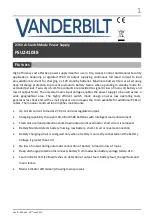
27.6V dc Switch Mode Power Supply  

PSU241038 


F

EATURES


High efficiency cost effective power supply ideal for use in Fire, Access Control and General Security 
applications.  Featuring  a  regulated  27.6V  dc  output  supplying  continuous  full  rated  current  to  load 
plus additional current for charging 2 x 12V standby batteries. Maximum battery life is assured using 
deep discharge protection to prevent premature battery failure when operating in standby mode for 
extended periods. Two sets of volt-free contacts are provided to signal (i) loss of mains (ii) battery and 
loss of output faults. The universal mains input voltage enables the power supply to be used across a 
wide  geographical  area.  The  highly  efficient  switch  mode  design  ensures  low  operating  costs, 
generates less heat and with a small physical size increases the room available for additional PCBs or 
cables. The modular construction simplifies maintenance.  


Up to 10A current to load at 27.6V dc nominal regulated output. 


Charging capability to support 18, 38 or 65Ah batteries with intelligent load enhancement. 


Electronic overload protection shuts down output until overload or short circuit is removed. 


Battery Monitor detects battery missing, low battery, short-circuit or reverse connection  


Battery charging circuit is energised only when a battery is correctly connected and the battery 

Voltage is greater than 14V. 


No loss of output during automatic connection of battery to load on loss of mains. 


Deep discharge protection disconnects battery from load when battery voltage falls to 21V. 


Fault indicator LED (Yellow) flashes on detection of output fault, battery fault, charger fault and 

mains failure. 


Mains indicator LED (Green) showing mains present. 

Summary of Contents for PSU241038

Page 1: ...operating costs generates less heat and with a small physical size increases the room available for additional PCBs or cables The modular construction simplifies maintenance Up to 10A current to load...

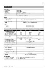
Page 2: ...max B With charging Imax A 220V With charging Imax A 110V 10 0 A 10 0 A 8 5 A 10 0 A 8 0 A 7 5 A 10 0 A 7 2 A 6 5 A Battery Charging Constant current bulk charging to 80 capacity within 24 hours Float...

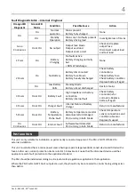
Page 3: ...D Normal operation Mains present Battery healthy None OPEN CLOSED Standby Mode Mains lost Battery driving load Investigate loss of mains CLOSED OPEN Fault Present Blown fuses Battery fault Overload In...

Page 4: ...attery connections for corrosion Replace battery if aged 4 PULSES ON or OFF Charger Fault Internal failure of battery charger Return to manufacturer 5 PULSES ON or OFF Battery Temperature Probe Fault...

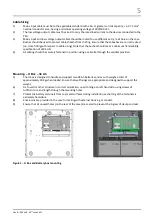
Page 5: ...ation of UL94 HB 4 All cabling should be securely fastened in position using a cable tie through the saddles provided Mounting H Box 38 Ah 5 The H box is designed to handle and support two 38 Ah batte...

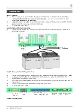
Page 6: ...lt outputs to the appropriate inputs of control equipment if remote fault monitoring is required Figure 4 Power Load and Battery connections 5 Connect the load output wiring as shown in Figure 4 Cable...

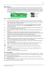
Page 7: ...ure sensor and battery connections are made according to figure 5 16 Re apply the mains power and verify that the yellow Fault LED stops flashing after about 20 s battery connection detected Verify th...

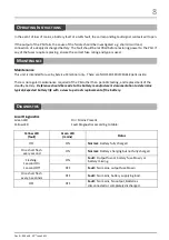
Page 8: ...intenance required of the PSU other than periodic testing and replacement of the standby battery Reference should be made to the battery manufacturer s documentation to determine typical expected batt...

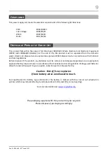
Page 9: ...tteries must be removed and disposed separately via an appropriate approved battery disposal route in accordance with all national and local regulations Package used batteries safely for onward transp...

Reviews: