background image


READ & SAVE THESE INSTRUCTIONS. 


This manual contains operating information and should be left with the unit. 
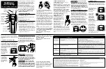
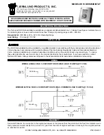


Model VS--D  

Steam Room Unit 

Installation & Operating Manual 

Edition 1.3.1


Installation in countries covered by EC Directives: 

This product meets the requirements of the RoHS Directive 2002/95/EEC 

This product will meet the requirements of the Low Voltage Safety Directive 2006/95/EEC 

and the EMC Directive 2004/108/EEC when installed in accordance with the instructions 

contained in this manual. 

Failure to comply with these instructions may invalidate the manufacturer's warranty or any 

certificate/declaration of conformance requested to be supplied with the unit. 

Summary of Contents for LE18-SR

Page 1: ...product meets the requirements of the RoHS Directive 2002 95 EEC This product will meet the requirements of the Low Voltage Safety Directive 2006 95 EEC and the EMC Directive 2004 108 EEC when installed in accordance with the instructions contained in this manual Failure to comply with these instructions may invalidate the manufacturer s warranty or any certificate declaration of conformance reque...

Page 2: ...Section General Page 2 of 24 18 Feb 2015 ...

Page 3: ...tion 10 3 0 Electrical Connections 11 3 1 Power Supply Connection 11 3 2 Control Connections 11 4 0 Controls 13 5 0 Status Indications 14 5 1 Normal Run Standby Start up No User Intervention Required 15 5 2 Fault Service Indications Requiring Operator Intervention 16 5 3 Resetting the fault condition 16 6 0 Cylinder Exchange 17 6 1 Procedure for Cylinder Exchange 17 6 2 Service and Maintenance 18 ...

Page 4: ... and create a trap Do not locate vented drain directly under the cabinet Important Electrical Connection Items Before commissioning the unit check that all electrical power connections including those at the terminals and contactor are tight The Vapac transformer must not be used to power other equipment To comply with EMC aspects see recommendations on page 10 Do not mount the unit close to a sou...

Page 5: ...ojecting type wall bolts or equivalent to mount the unit in position Don ts Don t mount the unit close to sources of strong electro magnetic emissions e g variable speed lift motor drives kVa transformers etc Don t mount the unit in an unventilated enclosure Don t mount in a position requiring ladder access to the unit Don t mount the unit behind a false ceiling or other situation where an unusual...

Page 6: ...s Cabinet Sz 1 5 18 kg h Models Left Top View Showing Steam O let position and wall mounting points Below Side View showing wall mounting points Left Bottom View Showing F Feed connection BSP male connection for flexible hose provided with unit D Drain connection 35 mm pipe ...

Page 7: ...30 55 kg h Models Left Top View Showing Steam O let position and wall mounting points Below Side View showing wall mounting points Left Bottom View Showing F Feed connection BSP male connection for flexible hose provided with unit D Drain connection 35 mm pipe ...

Page 8: ...unit of 300mm Do inject the essence into the steam line below the level of the cylinder and ensure that it can flow freely out with the flow of steam Any restrictions in flow will result in the essence solidifying and causing a restriction to flow of steam Do add extra insulation to steam hose for longer runs 2m 5m and in cold ambient conditions to avoid excess condensate and reduction in delivere...

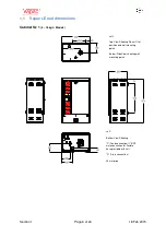
Page 9: ...Section 1 Page 9 of 24 18 Feb 2015 Vapac 0 I ...

Page 10: ... a seal If water seepage occurs undo the nut to wipe the washer clean and re seat it 2 2 Drain connection General Do s Do ensure metal drain and supply water pipework is grounded electrically close to the unit a ground earth stud is positioned on the underside of the cabinet Drain capacity per cylinder pump discharge rate of max 16 8 l min at 50 Hz 17 2 l min at 60 Hz Drain Connection Do s Do use ...

Page 11: ...trodes simultaneously This must be sized to suit the total maximum phase line current of the unit and should be located adjacent to the unit and be within easy reach and readily accessible The units can be connected for single or 3 phase operation and should be connected as shown below Three Phase connection Single Phase connection 3 2 Control Connections The unit is supplied with all the required...

Page 12: ...Section 3 Page 12 of 24 18 Feb 2015 Additionally terminals 1 2 provide a fused switched 230 V Phase Neutral supply to power an essence pump ...

Page 13: ...Section 4 Page 13 of 24 18 Feb 2015 4 0 Controls The position of the relevant controls are reproduced below ...

Page 14: ...d period Unit initialising IF REMAINS IN THIS STATE THEN UNIT DOES NOT HAVE A VALID UCP1 FITTED Prior to the start of the initialisation process the LEDs will flash Green Red Amber repeatedly for 10 seconds to check that the LEDs are operating correctly Remedy 1 Check that UCP1 is fitted to plug fitted to CR4 pins 7 8 ...

Page 15: ... following table User LEDs Description 1 OFF Unit in shutdown 2 OFF Unit in standby 3 Green Amber Flashing Variable RED Flashing Variable Period or ON Unit in Startup Unit Online The above are purely indications of the current state of the unit and require no action from the operator When the state changes the indication will automatically change ...

Page 16: ...ain control PCB If this is also correct then either the daughter board or the main control PCB is faulty Once the fault has been cleared the LED indications will revert back to the cylinders current state 5 Service the unit by following the instructions on pages 15 16 5 3 Resetting the fault condition Once the fault has been rectified the unit may be re started by powering the unit down at the mai...

Page 17: ...r of sediment 7 The drain pump can be removed for inspection cleaning By following the instructions for the drain pump removal and cleaning below 8 With the pump back in position after cleaning insert the cylinder into the feed drain manifold pushing it down firmly and reconnect the steam hose 9 The electrode caps must be reconnected in the same sequence in accordance with the details on the colla...

Page 18: ...e same time 6 2 1 Feed Valve with Strainer The nylon bodied solenoid valve incorporates a small nylon strainer which is a push fit in the 3 4 inlet of the valve With a new plumbing installation residual loose solid material in the pipework could partially block the strainer after start up If for this or any other reason a restriction of the water flow is suspected outside of supply pressure consid...

Page 19: ...using or pipework 2 Remove the two screws holding the pump cover lift clear 3 Undo the three screws holding the pump body to the feed drain manifold and remove it any water trapped in the pump will be released at this point 4 Fit the replacement pump by following the above steps in reverse order Ensuring that the O ring surrounding the impeller housing is correctly seated and that it mates correct...

Page 20: ...l Supply Ph s Ph N Ph N 3Ph 3Ph 3Ph 3Ph 3Ph 3Ph 3Ph 3Ph 3Ph 3Ph 3Ph 3Ph No of electrodes 2 2 3 3 3 3 3 3 6 6 6 6 6 6 Full load Current A 17 30 5 21 5 20 5 19 5 35 5 34 32 5 54 51 49 66 62 60 Maximum overcurrent A 25 5 45 75 23 65 22 55 21 45 39 05 37 4 35 75 59 4 56 1 53 9 72 6 68 2 66 CSP setting A 17 30 5 21 5 20 5 19 5 35 5 34 32 5 27 25 5 24 5 33 31 30 Fuse Rating phase A 32 50 32 32 25 50 50 ...

Page 21: ...oid Water Feed Valve CYL 1 Y1A K1 0v 24v 0v DO1 24v DO1 24v DO3 0v DO3 0v DO2 24v DO2 DI COM DI 1 24v IN 24v OUT AI 3 IN AI 2 IN AI 1 IN AI 1 2 Ref 11 12 1 2 3 4 6 5 7 8 9 10 8 7 6 5 3 4 2 1 12 11 10 9 CR2 four resistive inputs 0V Brown Grey Orange Grey DAUGHTER BOARD Part Number 1150633 3 Violet 29 22 89 81 55 51 42 41 31 32 CR6 CR7 CR2 CR4 47 48 N 2 1 22 F3 2A A3 A2 A3 20 Brown 1 2 3 4 5 6 7 8 9...

Page 22: ...s not connected Water connected but not reaching cylinder Checks Check water stop valve is open Check internal Vapac hose connections for a leak Automatic Stop Drain Fault indicated Possibilities Drain pump function impaired Checks If pump will not function empty cylinder by disconnecting the water supply hose between the tundish and the cylinder at the tundish fill cup and lowering it to drain th...

Page 23: ......

Page 24: ...England by Vapac Humidity Control Ltd 0410272 18th February 2015 Vapac Humidity Control Ltd reserve the right to change the design or specification of the equipment described in this manual without prior notice ...

Reviews: