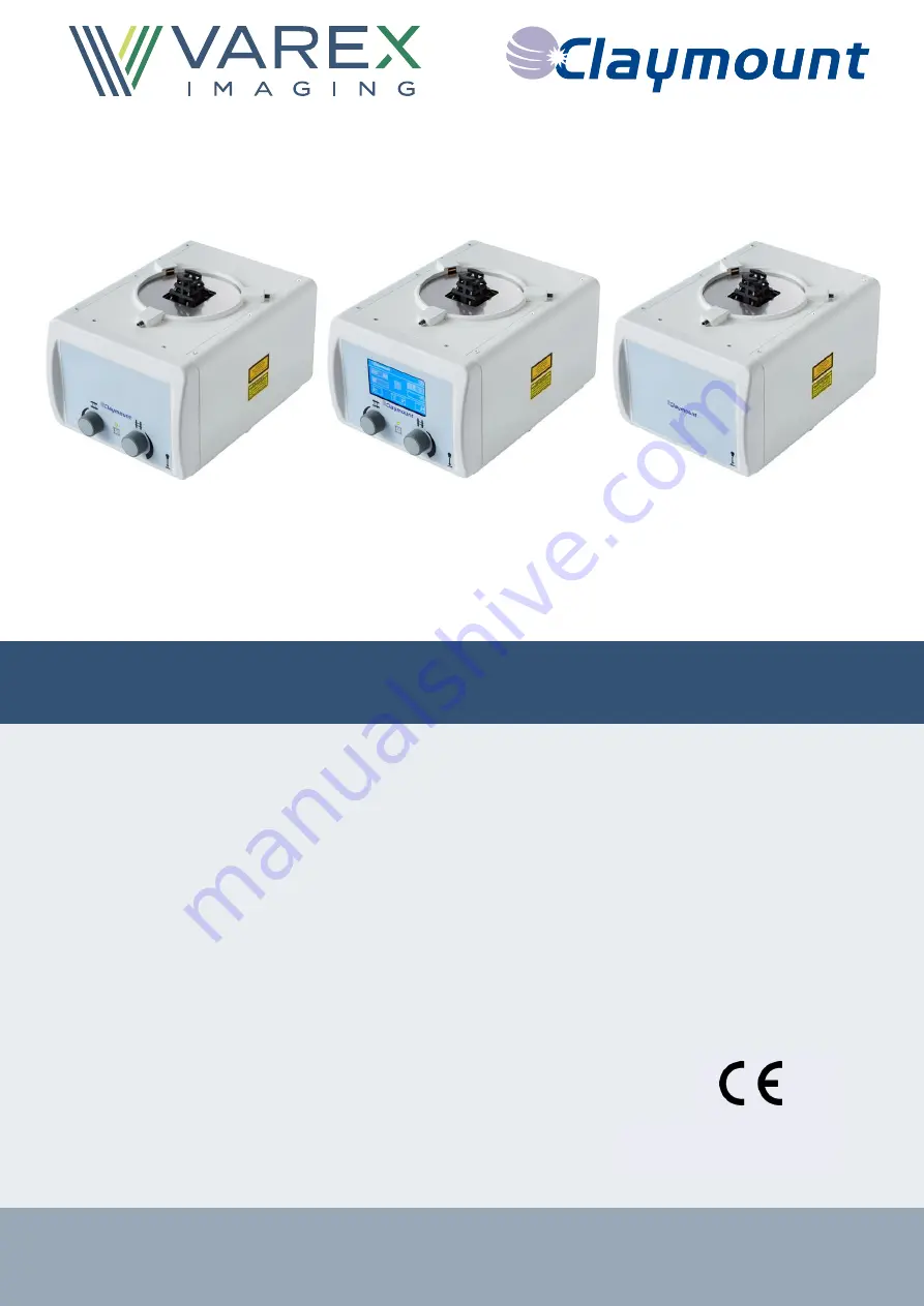
background image


UM50566-EN, Revision: 3.0  


www.vareximaging.com 


0120


Optica 30/40/50 series 

User Manual


Optica 30 

Optica 40 

Optica 50 

Summary of Contents for Optica 30 Series

Page 1: ...UM50566 EN Revision 3 0 www vareximaging com 0120 Optica 30 40 50 series User Manual Optica 30 Optica 40 Optica 50...

Page 2: ...1 2 4 Principle of operation 11 2 5 Known contraindication s 12 2 6 Restrictions on use 12 2 7 Overview of the collimator 12 2 8 Bucky laser 13 2 9 Applied parts 13 2 10 Accessories 13 2 11 Classifica...

Page 3: ...ex Imaging Nederland B V products Warranty The product has the warranty provisions of our general conditions The warranty on your equipment will be void if Service and maintenance are not carried out...

Page 4: ...eries Touchscreen Control knobs Status LED Light button 30 x x x 40 x x x x 50 x means that this feature is present means that this feature is absent The Optica 50 series is meant for remote control o...

Page 5: ...rex Imaging Nederland B V is not liable if the provided instructions are not complied with Varex Imaging Nederland B V is not liable if one or more of the following cases apply Modification or repairi...

Page 6: ...zed personnel Varex Imaging Nederland B V cannot be held responsible for injuries or damage to equipment WARNING Disconnect power supply before opening collimator WARNING Do not use the collimator if...

Page 7: ...e product label or other markings on the outside of the collimator are missing Requirements for SERVICE PERSONNEL The device may only be installed repaired or serviced by qualified SERVICE PERSONNEL i...

Page 8: ...onal feature Explanatory warning for hazardous optical radiation Explanatory warning for laser radiation optional feature Indication cross shutters Indication long shutters Operate field light indicat...

Page 9: ...imaging com Symbol Explanation Tilting angle Setup collimator Return to previous screen Accept numeric keyboard value Cancel numeric keyboard value Delete entered digit on numeric keyboard Restart col...

Page 10: ...directly The packaging contains the following components Amount Description Reference 1 Optica 30 40 50 series CF002 Configuration with automatic filters CF004 Configuration without automatic filters...

Page 11: ...of lead shutters are located near the focus of the X ray beam two pairs are located near the exit window of the collimator The latter shutters serve to accurately define the X ray field edges The X ra...

Page 12: ...tance of 30 cm Otherwise the performance of the device can be negatively influenced 2 7 Overview of the collimator A Fixing flange B Control knob Cross shutters Optica 30 40 Series only C Control knob...

Page 13: ...nd this point could cause the following inconveniences Breakage of the tape or Distortion of the tape or Impossibility of retracting the tape into its housing NOTE Do not extend the tape beyond the in...

Page 14: ...e Electrical safety classification Class I IEC 60601 1 Applied Part Not applicable IEC 60601 1 Mode of operation Continuous operation IEC 60601 1 Ingress protection classification IP20 IEC 60529 Laser...

Page 15: ...power ON self test can be Successful The color of the status LED is green not flashing Optica 30 40 Series only additional filtering is not applied and the shutters are completely closed The Main scre...

Page 16: ...s are indicated by a number and explained in 3 3 The collimator shows a popup error message on the touch screen Optica 40 Series only WARNING only the first detected fault condition is displayed on th...

Page 17: ...R ON self test and normal OPERATING MODE the collimator software can detect fault conditions see 3 3 Collimator Mode Color of the status LED Explanation of the color indication POWER ON Green Flashing...

Page 18: ...on message If the error persists do not use the collimator contact service engineer 70 Long and or cross shutter sensor s fault Restart the collimator by selecting in the fault condition message If th...

Page 19: ...M50566 EN Optica 30 40 50 series Revision 3 0 Date of release 2019 01 09 19 36 www vareximaging com 3 4 Collimator functions during OPERATING MODE Optica 40 Series only Example for pre set selecting S...

Page 20: ...User Manual UM50566 EN Optica 30 40 50 series Revision 3 0 Date of release 2019 01 09 20 36 www vareximaging com Example for manually selecting SID to 110 cm...

Page 21: ...g the field size by turning the control knobs 2 Set the field size by predefined values 3 Set the field size manually by entering the field size values For each field size selection method the corresp...

Page 22: ...Manual UM50566 EN Optica 30 40 50 series Revision 3 0 Date of release 2019 01 09 22 36 www vareximaging com Method 3 Set the field size manually The field size X x Y can be selected manually in centim...

Page 23: ...User Manual UM50566 EN Optica 30 40 50 series Revision 3 0 Date of release 2019 01 09 23 36 www vareximaging com...

Page 24: ...and OFF simultaneously with the light button on the display or the button on the front panel Field light and bucky laser ON OFF is indicated on the touch screen as Field light ON Field light OFF Bucky...

Page 25: ...ribed in the table Symbol Definition MANUAL operating mode Collimator operating is controlled by the Collimator user interface Control knobs Light field and Laser button and Touch screen AUTOMATIC ope...

Page 26: ...ing com Additional filter selection When the button for additional filters is pressed on the touch screen a filter combination can be selected and will be displayed Parameter default settings See the...

Page 27: ...t they are operating normally WARNING Use of accessories transducers and cables other than those specified or provided by the manufacturer of this equipment could result in increased electromagnetic e...

Page 28: ...possible injury to the user Cleaning recommendations Make sure the collimator is switched OFF see 3 1 for instructions WARNING Use of abrasive cleaning could result in deterioration of the collimator...

Page 29: ...sal This Collimator contains substances that can be hazardous to the environment and care should be taken when disposed of The Collimator is marked with the following symbol Follow national and local...

Page 30: ...s distance SID 1 m EN 60601 2 54 203 8 4 150 mm Square X ray field selection Min 00 x 00 cm Max 48 x 48 cm 1 at 1 m SID to reach 43 x 43 cm at 90 cm SID Motor controlled shutters Yes Motor controlled...

Page 31: ...ive humidity 30 95 non condensing Atm Pressure 700 1060 hPa 6 1 Product label The figure below shows the information provided on the product label Where Model Optica XX represents the model name of th...

Page 32: ...OPTICA XX XXXXX NN LLL XXXXXXXXXXXX YYYY MM DD Model REF SN Min inherent filtration Al Equi v 1 2mmAl 75 kV X ray rating up to 150 kVp IP20 01 0XXXXXXXXXXXX 11 XXXXXX 21 WOXXXXXX E XX This product co...

Page 33: ...User Manual UM50566 EN Optica 30 40 50 series Revision 3 0 Date of release 2019 01 09 33 36 www vareximaging com This page is intentionally left blank...

Page 34: ...User Manual UM50566 EN Optica 30 40 50 series Revision 3 0 Date of release 2019 01 09 34 36 www vareximaging com This page is intentionally left blank...

Page 35: ...User Manual UM50566 EN Optica 30 40 50 series Revision 3 0 Date of release 2019 01 09 35 36 www vareximaging com This page is intentionally left blank...

Page 36: ...om Varex Imaging Philippines Inc Philippines t 63 49 5024 520 t 63 49 5024 521 f 63 49 5024 500 f 63 2 8076 472 Philippines CNC vareximaging com Varex Imaging Technology Beijing Co Ltd China t 86 10 6...

Reviews: