967946-02
ENGLISH
1
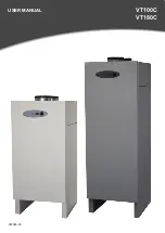
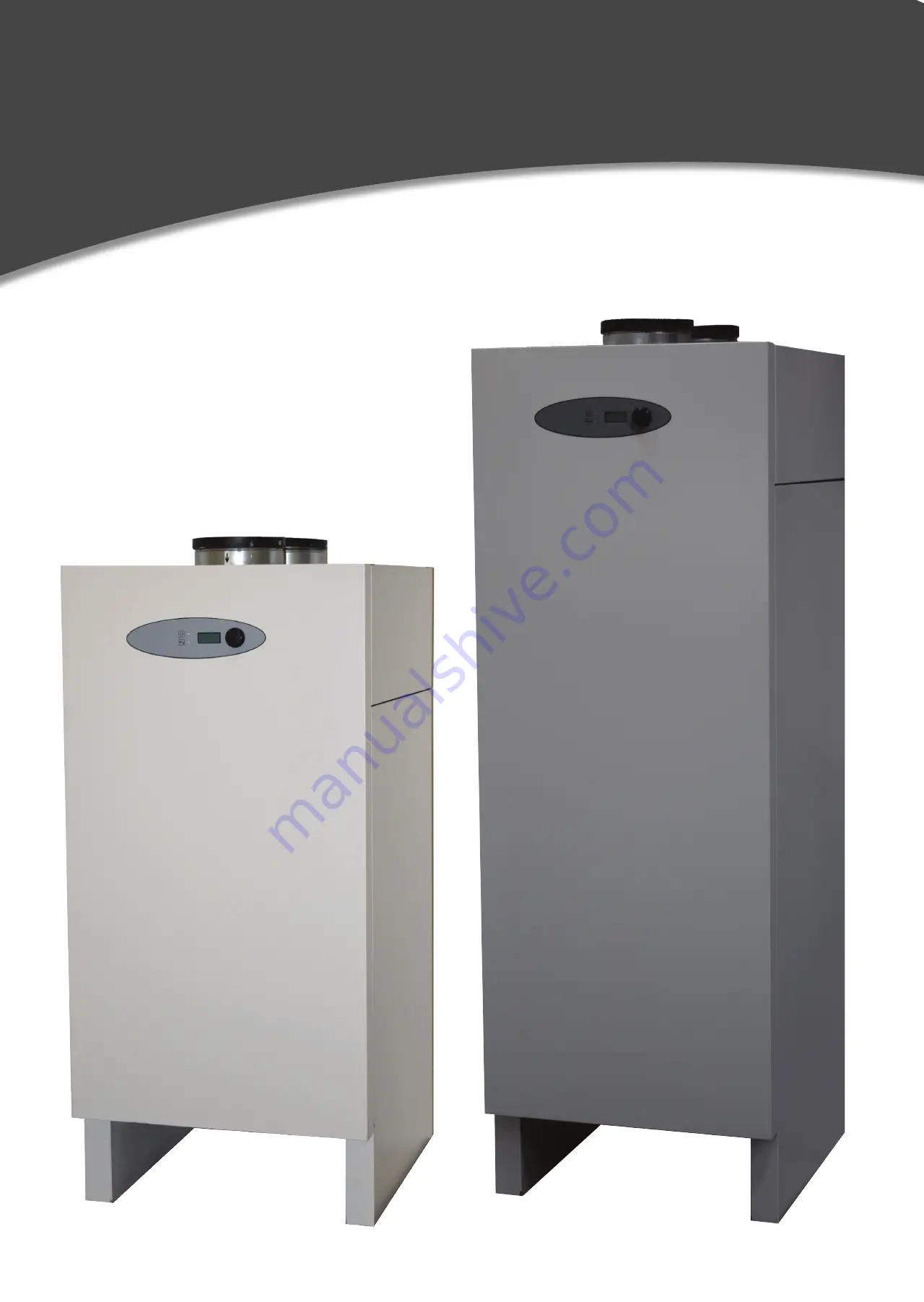
USER MANUAL
VT100C
VT180C
Page 1: ...967946 02 ENGLISH 1 USER MANUAL VT100C VT180C...
Page 2: ...n 14 Insulation of the installation 14 Preparation for installation 15 Cold water connection scheme 16 DHW production 17 ELECTRICAL INSTALLATION 18 Electrical diagram 18 User interface 19 Display view...
Page 3: ...ng of a solar cell installation 34 Wiring recommendations 34 Use of holiday function 35 Use of boost function 35 Use of external controlled DHW production 34 Use of timer function 36 SUPPLEMENTARY ELE...
Page 4: ...rer s instructions as well as the respect of the actual local national and international standards regulations and laws as well as the state of the art regarding water and electrical installations is...
Page 5: ...The energy is transported in the HP circuit from the evaporator to the compressor In the compressor the energy will be transformed to a higher temperature level This process only need 30 of the therm...
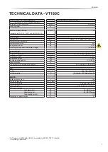
Page 6: ...er content Working pressure Water temperature Water capacity Water connections Cold water inlet Hot water outlet Condensation water Protection of water ingress TECHNICAL DATA VT100C M profile W dB A m...
Page 7: ...water content Working pressure Water temperature Water capacity Water connections Cold water inlet Hot water outlet Condensation water Protection of water ingress TECHNICAL DATA VT180C L profile W dB...
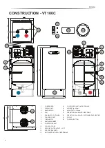
Page 8: ...ER 6 CENSOR POCKET 7 THERMOSTAT 8 HEATING ELEMENT 9 CONTROLLER UNIT 10 FAN CAPACITORS 11 DEFROST WATER OUTLET 1 2 PT 12 SUPPORT BRACKETS 13 HOT WATER OUTLET 3 4 BSP FEMALE 14 COLD WATER INLET 3 4 BSP...
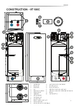
Page 9: ...2 SUPPORT BRACKETS 13 HOT WATER OUTLET 3 4 BSP FEMALE 20 19 17 18 167 CONSTRUCTION VT180C 85 16 15 13 14 104 300 1576 1540 540 590 575 200 170 267 308 1 2 7 2 13 14 3 4 9 10 11 5 6 2 8 12 12 11 14 COL...
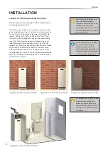
Page 10: ...s CHOICE OF THE INSTALLATION LOCATION Wherever possible the heat pump should be installed close to the existing hot water conduit The location must be indoors in a frost free environment with a frost...
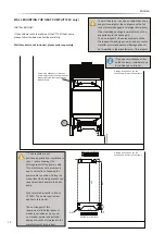
Page 11: ...ld cause water leakage and this will cause exclusion of warranty 1 90 Level of defrost water outlet Applicable for both VT100C and VT180C Applicable for both VT100C and VT180C To reach the hot and col...
Page 12: ...installer or due to low free space in room The brackets are not positioned equally from center due to pos 1 above drawing the holding bracket of the power cable This bracket may not be removed due to...
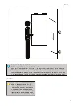
Page 13: ...ositioned onto the lower bracket 2 else adjust the bracket a bit Gently press down and pull the heat pump towards you to check if it is safe enough to start connecting water supply On a daily basis it...
Page 14: ...regulations and standards Generally the water inlet is protected by a safety device safety valve and drain combined as well as a backflow protection retention valve and a shunt valve These fittings ar...
Page 15: ...and the air outlet exhausts the air into the same room This installation mode needs some requirements In this installation mode the fan speed should be adjusted at high Anyhow if you should want to c...
Page 16: ...essure 5 Safety valve 1 max pressure 1 MPa 10 bar Discharge pipe connected to safety valve must be installed downwards and in frost free environment The water may drip from the discharge pipe of the p...
Page 17: ...e Tmin is achieved with heat pump and supplementary heating energy source selection HP EL if selected The heat pump operates with a hysteresis of 1 3 C around the DHW setpoint The supplementary heatin...
Page 18: ...pacitor fan speed Fan 6 F R2E180 Start capacitor compressor Compressor 80 F DLE6 5CN Heating element 2kW Thermostat for heating element X Thermostatic max switch Compressor DLE6 5CN Fan R2E180 Solenoi...
Page 19: ...n this parameter appears on the display It indicates the current DHW temperature Evapor 5 C Evaporator temperature This parameter displays the current evaporator temperature Alarm 0 0 0 Alarm display...
Page 20: ...Example Set the clock to 06 in morning H Pump HP EL This parameter displays the energy source for your DHW production The energy source can be selected with the rotary push button The possible select...
Page 21: ...h button The possible selection are OFF 1 week 2 weeks 3 weeks 3 days Manual When the holiday mode is activated T2 min is the safety level for frost protection Man Days 1 This parameter displays the n...
Page 22: ...User interface An interruption of the HP fan operation e g because the water temperature setpoint has been reached resets the Fan Pause function timer The timer restarts together with the HP operatio...
Page 23: ...resumes If there are simultaneous alarms the alarms are displayed up to 3 alarms in a sequence according to their priority Special handling of pressostat switch alarms alarm 5 6 The pressostat switch...
Page 24: ...emperature is not reached The timer function is not set before activating it ERROR NO LED INDICATOR 1 17 AND 18 2 17 AND 18 ERROR NO LED INDICATOR 3 17 4 17 5 17 6 17 ERROR NO LED INDICATOR 8 17 9 17...
Page 25: ...ff If the evaporator temperature reaches 5 C the solenoid valve closes and the fan restarts If the temperature for the evaporator does not reach 5 C within 20 minutes the defrosting procedure will sto...
Page 26: ...ing the legionella protection cycle is higher than the needed output for the legionella pro tection procedure THERMAL DISINFECTION LEGIONELLA PROTECTION The procedure must be activated in the paramete...
Page 27: ...ate the button until ON appears Press the rotary button once and legionella will be activated The heat pump will heat up the water to 60 C 1 C in hysteresis by only use of the compressor Note If the h...
Page 28: ...ent automatically Note When activated the lower LED don t lit up for showing activation of the supplementary heating element User menu In the Water status menu the user can see when the 60 C 1 C in hy...
Page 29: ...without any surveillance of 1 hour This function applies only when the legionella sequence is activated through the installers menu User menu When the heat pump returns to normal operating mode the u...
Page 30: ...lls that the heat pump is running in normal operating mode when the legionella alarm is activated User menu The user can push the button on the Alarm menu to acknowledge the alarm Note If the error ap...
Page 31: ...pressure level of the security group is met the security valve opens and releases excess water pressure to the drain This water release and even permanent releases in form of dropping is absolutely no...
Page 32: ...t and the air outlet are located at the top of the heat pump The ducts should be used with thermal and acoustic insulation The duct connections are 160 mm To ensure sufficient air flow the following r...
Page 33: ...outlet goes out then use the VT100C and VT180C as an 5 C unit as long as the ambient air temperature doesn t go below 5 C else use an 10 C unit Air fan defrosting mode only or Solenoid valve hot gas...
Page 34: ...djusted Please do select an appropriate power level in order to ensure a smooth operating consider the instructions of the inverter producer See wiring diagram page 18 Electrical installation WIRING R...
Page 35: ...n The holiday parameter menu has 5 possible choices 1 week 2 weeks 3 weeks 3 days for an extra long weekend Manually setting of days 1 99 USE OF BOOST FUNCTION The Boost mode gives you the possibility...
Page 36: ...is set to OFF User menu Press the rotary button until the text flashes and then rotate the button until ON appears Press the rotary button once and timer will be activated Note LED light will appear...
Page 37: ...e button The text will flash and rotate the button to adjust to desired starting hours User menu To start the timer function the user must set the start minutes for when the heat pump should start pro...
Page 38: ...the heat pump should stop produce hot water Use the rotary button to scroll to Stop HP and press the button The text will flash and rotate the button to adjust to desired stop minutes The timer funct...
Page 39: ...water temperature is below Tmin the heating element will support the heating until the temperature Tmin is reached The heating element is quipped with a safety and an operational thermostat The safet...
Page 40: ...the displays for alarms To clean air in and outlet from dust To check the installation for leakages To check and clean the drain connector hose To inform the installer if necessary MAINTENANCE BY THE...
Page 41: ...SPARE PARTS Right to change of specification without prior notice reserved ENGLISH 41...