background image

Installation, Operating & 
Maintenance Instructions 


943070EA 

Edition 2018-06-19 


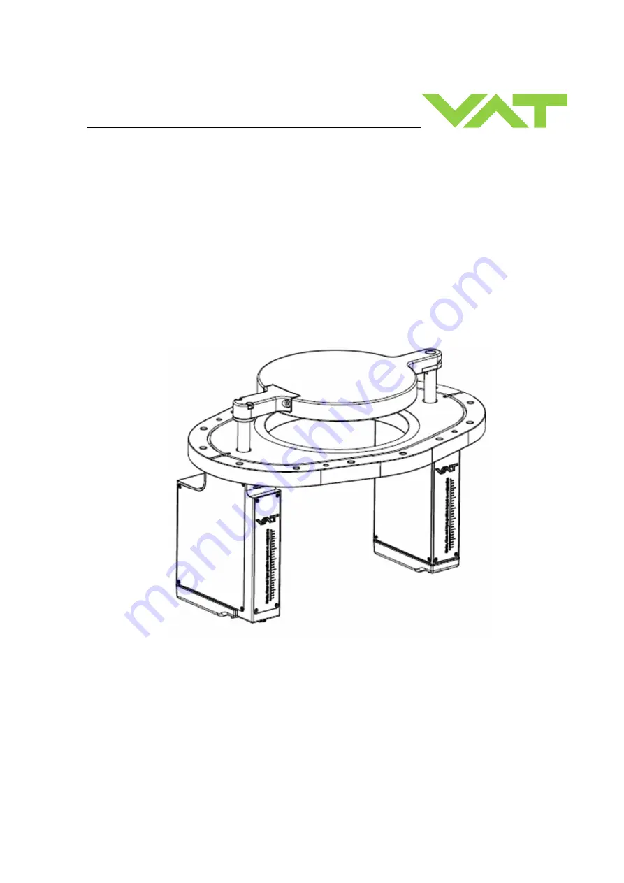
Symmetrical flow control & isolation valve 


Series 670  
DN 250 mm (I. D. 14") 

 
This manual is valid for the following product ordering number 
 

67048-PH52-ACF1 


Summary of Contents for 670 Series

Page 1: ...Operating Maintenance Instructions 943070EA Edition 2018 06 19 Symmetrical flow control isolation valve Series 670 DN 250 mm I D 14 This manual is valid for the following product ordering number 6704...

Page 2: ...duplicated or distributed without written permission from VAT Offenders are liable to pay damages The original VAT firmware and updated state of the art versions of the VAT firmware are intended for u...

Page 3: ...on 8 4 Installation 9 4 1 Unpacking 9 4 2 Installation into the system 11 4 2 1 Installation space condition 12 4 2 2 Installation overview 13 4 2 3 Installation procedure 14 4 3 Tightening torque 15...

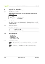
Page 4: ...ean and dry vacuum applications only Other applications are only allowed with the written permission of VAT 1 3 Used abbreviations Abbreviation Description SFV Symmetrical flow valve CPA Control perfo...

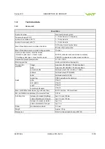
Page 5: ...s Admissible operating temperature 10 C to 120 C Mounting position Horizontal actuators downwards Process side materials flange Aluminum EN AW 6061 T6 hard anodized plate Aluminum EN AW 6061 T6 hard a...

Page 6: ...ion Operating Maintenance Instructions are an integral part of a comprehensive documentation belonging to a complete technical system They must be stored together with the other documentation and acce...

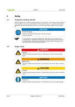
Page 7: ...ons WARNING Unqualified personnel Inappropriate handling may cause serious injury or property damage Only qualified personnel are allowed to carry out the described work 2 4 Safety labels Label Part N...

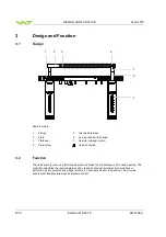
Page 8: ...epper motor 4 Plate screw Valve seat side 3 2 Function The valve plate 2 acts as a throttling element and varies the conductance of the valve opening The controller calculates the required plate posit...

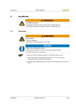
Page 9: ...ining Use a crane to lift valves DN 200 8 and larger NOTICE Physical overstraining at actuators Inappropriate handling with the valve may cause in damage of actuator Do not place the valve on the actu...

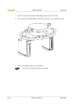
Page 10: ...transport case and remove inside packing material as far as necessary 2 Use a crane and lifting attachments 4 M10 thru to lift the valve See example figure below 3 Lift the valve carefully and place i...

Page 11: ...ower supply Connect all cables exactly as shown in the following schematic NOTICE Burned connector pins spark Connector pins or electronic parts could damage if plugged and unplugged under power Do no...

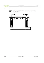
Page 12: ...INSTALLATION Series 670 12 39 Edition 2018 06 19 943070EA 4 2 1 Installation space condition Install the valve with actuators with space a for dismantling and air circulation as shown in figure below...

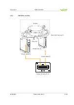
Page 13: ...es 670 INSTALLATION 943070EA Edition 2018 06 19 13 39 4 2 2 Installation overview Chamber External Controller IC2 3 Pump side Symmetrical flow valve 1 Heating device 4 Actuator cables 2 Actuator cable...

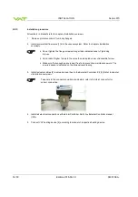
Page 14: ...orces to the valve than indicated under Admissible forces Make sure that enough space is kept free to do preventive maintenance work The required space is indicated on the dimensional drawing 3 Instal...

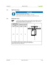
Page 15: ...es Forces from evacuating the system from the weight of other components and from baking can lead to deformation and malfunctioning of the valve Stress has to be relieved by suitable means e g bellows...

Page 16: ...el Inappropriate handling may cause serious injury or property damage Only qualified personnel are allowed to carry out the described work CAUTION Valve opening Risk of injury Do not operating before...

Page 17: ...Edition 2018 06 19 17 39 6 Trouble shooting For Trouble shooting refer to External Controller manual If you need any further information please contact one of our service centers You can find the addr...

Page 18: ...during operation Once heating is switched off valve and system await until the valve is cooled down complete before doing any work CAUTION Valve opening Risk of injury Human body parts must be kept ou...

Page 19: ...her the maintenance can be performed by the customer or has to be carried out by VAT www vatvalve com The fabrication number on the valve has always to be specified Refer to chapter 1 1 Identification...

Page 20: ...m wiper Isopropyl alcohol Clean room gloves Electrical power is required Description Required tool Use the CPA 4 0 which is integrated in the IC2 controller 1 Go to LOCAL mode CPA 2 Select position 20...

Page 21: ...right side at plate Do not remove the screw Allen wrench 5 mm 8 Loosen the plate screws left side at plate Do not remove the screw Allen wrench 4 mm 9 Lift the plate by hand carefully and remove it fr...

Page 22: ...shaft and the seal groove O ring removal tool Cleanroom wiper Isopropyl alcohol 16 Clean the internal valve Cleanroom wiper Isopropyl alcohol 17 Plate installation Take care to heating connection It i...

Page 23: ...screws with 5 Nm Allen torque wrench 4 mm 21 Fasten the plate screws with 8 Nm Allen torque wrench 5 mm 22 Switch ON the power supply 23 Select LOCAL CPA If PFO available on IC2 controller proceed wit...

Page 24: ...Required tool 25 Select CLOSE the valve is executing Homing and moves to close position CPA 26 Close the service cover Refer to manual of customized process chamber 27 Connect the heater cables 28 Sw...

Page 25: ...power is required Description Required tool 1 Use the description of chapter 7 2 1 Removing the plate and plate seal replacement to remove the plate Only steps 1 to 9 are needed 2 Place the plate on...

Page 26: ...l 7 Disconnect the power cable Pozidriv screwdriver No 1 Take care to sealing surface of flange and actuator 8 Loosen the actuator screws white arrows complete and remove the actuators Make sure that...

Page 27: ...INTENANCE 943070EA Edition 2018 06 19 27 39 Description Required tool Take care to sealing surface and valve surface 9 Remove the actuator Take care to sealing surface and valve surface 10 Insert the...

Page 28: ...hand Allen wrench 4mm 12 Fasten the actuator screws with 8Nm Allen torque wrench 4mm 13 Connect the power cables Take care to the connector position at actuators refer to 3 dots at connector for corre...

Page 29: ...keyboard 16 Wait until Homing is finished The position of valve is now 20 open The SFV Axis Initialization Mode will be automatically disabled after the homing CPA 17 Switch OFF the power supply 18 In...

Page 30: ...pairs may only be carried out by the VAT service staff In exceptional cases the customer is allowed to carry out the repairs but only with the prior consent of VAT Please contact one of our service ce...

Page 31: ...scribed work 9 1 Dismounting NOTICE Contamination Gate and other parts of the valve could be contaminated Always wear clean room gloves when handling the valve NOTICE Valve in open position Valve body...

Page 32: ...humidity between 10 and 70 temperature between 10 C and 50 C non condensing environment NOTICE Inappropriate packaging Product may get damaged if inappropriate packaging material is used Always use t...

Page 33: ...is used Always use the original packaging material and handle product with care When returning products to VAT please fill out the VAT form Declaration of Chemical Contamination and send it to VAT in...

Page 34: ...A 10 2 Transport NOTICE Inappropriate packaging Product may get damaged if inappropriate packaging material is used Always use the original packaging material and handle product with care VAT disclaim...

Page 35: ...Series 670 DISPOSAL 943070EA Edition 2018 06 19 35 39 11 Disposal WARNING Harmful substances Environmental pollution Discard products and parts according to the local regulations...

Page 36: ...that the appropriate spare parts are supplied VAT makes a difference between spare parts that may be replaced by the customer and those that need to be replaced by the VAT service staff The following...

Page 37: ...Series 670 SPARE PARTS 943070EA Edition 2018 06 19 37 39 Item Description Part number 15 Wiper ring optional 2 567449 110 Plate seal 1 393283 100 Actuator seal 2 N 5100 221...

Page 38: ...APPENDIX Series 670 38 39 Edition 2018 06 19 943070EA 13 Appendix No information entered on time...

Page 39: ...Series 670 943070EA Edition 2018 06 19 39 39 This Page Intentionally Left Blank...

Reviews: