background image

VideoJet 100

VideoJet 100

VideoJet 100

VideoJet 100

Manual

Summary of Contents for VideoJet 100

Page 1: ...VideoJet 100 VideoJet 100 VideoJet 100 VideoJet 100 Manual...

Page 2: ...AG Note This manual was compiled with the greatest of care and all informa tion double checked At the time of printing the description was complete and correct Because of the further development of pr...

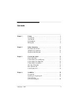
Page 3: ...tion 12 Repairs and maintenance 12 Chapter 3 Product description 13 Scope of delivery 13 Preconditions for commissioning 13 Preconditions for configuration 13 Preconditions for operation 14 Overview o...

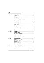
Page 4: ...tings 52 Harddisk settings 54 Interface settings 66 Service settings 68 Function test 74 Chapter 6 Operation 75 Operation with the Microsoft Internet Explorer 75 Hardware connection between VideoJet 1...

Page 5: ...Contents 5 VideoJet 100 Application examples 105 Specifications 107 Chapter 9 Index 109...

Page 6: ...Contents 6 VideoJet 100...

Page 7: ...In this manual the following symbols and notations are used to draw attention to special situations Hazard or Attention This symbol indicates that failure to follow the safety instructions given may d...

Page 8: ...owing typographic conventions are used in this manual Configuration Menu names and window and button names and parameters Enter C Key names Ctrl C Two or more keys that are pressed simul taneously pin...

Page 9: ...manual please contact VCS Video Communication Systems AG Forchheimer Stra e 4 D 90425 N rnberg Phone 49 0 911 93 45 6 0 Fax 49 0 911 93 45 6 66 info vcs com EU Guidelines The Network Video Server Vid...

Page 10: ...Preface 10 VideoJet 100...

Page 11: ...ly unit and device only in a dry place pro tected against the elements If you are uncertain about the safe operation of the unit shut it down immediately and secure it to prevent any unauthorised star...

Page 12: ...llation and operating work described in this manual All other work beyond this may lead to injuries to per sons and damage to the system or other equipment Repairs and maintenance Never open the housi...

Page 13: ...ing Computer with operating system Windows 95 98 NT and a gate way to the network Microsoft Internet Explorer web browser from Version 5 or free serial interface and terminal program Preconditions for...

Page 14: ...its the simple installation and configuration of CCTV systems The VideoJet 100 is available in three versions as transmitter as transmitter with integrated hard disk for local long term recording and...

Page 15: ...ideo transmission in real time to several recei vers A precondition for this is the implementation of the UDP User Datagram Protocol in the network Remote control For remote control of external equipm...

Page 16: ...ral Ethernet interface 10 100 Base T 2 transparent bidirectional data channels via serial interfaces RS232 RS422 RS485 and RS232 Remote control of all internal functions via UDP IP Password protection...

Page 17: ...jack bush for connection of a loudspeaker 5 Screw clamp INPUTS for connection of alarm sensors or switches 6 Screw clamp OUTPUTS relay outputs for switching of external devices e g lamps 7 Serial int...

Page 18: ...LEDs OUTPUTS light up green when the corresponding relay is switched 14 LED COM lights up yellow when data is transmitted over the serial interfaces 15 LEDs ETHERNET green LED lights up when the unit...

Page 19: ...ons use only the supplied or suitable cables which also prevent any electrical interference where necessary Lay and install all cables in such a way that they cannot be damaged and ensure sufficient s...

Page 20: ...is not looped through e g with a T piece Receiver Connect a video monitor to the BNC jack VIDEO using a video cable 75 Ohm BNC connector Network connection You can connect the VideoJet 100 either dir...

Page 21: ...ating NO contact is used the contact 5V must be connected to the corresponding INPUT connection The signal generator is then connected between the other contact of the INPUT connection and the contact...

Page 22: ...via the jacks AUDIO IN and OUT The audio signals are transmitted bidirectionally and simulta neously with the video signals This allows for example a loud speaker or door intercom system at the survei...

Page 23: ...transparent data is only possible when a video connection has been made COM1 COM2 RS232 RS422 485 RS232 1 DCD data carrier detect 2 RxD receive data RxD receive data minus RxD receive data 3 TxD tran...

Page 24: ...it into a fused mains power plug socket The green LED POWER on the front of the VideoJet 100 lights up and the server is ready for operation When the network connection has been correctly made the gre...

Page 25: ...erTerminal as termi nal program First disconnect the VideoJet 100 from the network Connect the sub D jack COM2 of the VideoJet 100 to a free serial port of the computer Configuring the terminal progra...

Page 26: ...p page If necessary switch off the local echo so that input values are not repeated Enter only one command at a time and do not terminate this input by pressing the ENTER key After entering a value e...

Page 27: ...inal program you can check and if necessary change further fundamental parameters For this you can use the following commands Displays the Help page i Displays the current IP address and prompts the u...

Page 28: ...Installation 28 VideoJet 100...

Page 29: ...VideoJet 100 to be operated in your network it has to be assigned a valid IP address for your network The following address has been preset at the factory 192 168 0 1 Start the web browser Enter the...

Page 30: ...wing text field to signal your access authorisation Click on OK to initiate the check of the password If the password is correct you will see the Live Picture page with the video window resp gain acce...

Page 31: ...language selection date and time Camera names display stamping Video settings Audio settings Alarm configuration video sensor Configuration and operation of relay outputs Configuration of hard disk r...

Page 32: ...button Configuration to switch to the configuration pages Page Identification is displayed Click in a text field and enter new values or texts or click on a list field to select a different setting Ex...

Page 33: ...for the VideoJet 100 here With appropriate configu ration the name will be displayed in the video window Unit ID Each VideoJet 100 should have a clearly defined designation which you can enter here as...

Page 34: ...ure or the configuration settings dis played but you cannot change them Password You can define and change passwords for access to the device when you are working with the authorisation level Service...

Page 35: ...current date here As the system time is controlled by the internal calendar clock the day of the week does not have to be entered It is added automatically Time Enter the current time here or click t...

Page 36: ...era on input VIDEO Display stamping You can configure the device so that the camera name device name time and alarm source are displayed in the video image Select Top if the names are to be displayed...

Page 37: ...g video signal in the video image for information Select Off to never display the alarm source or On alarm if the alarm source is only to be displayed in the event of an alarm Or select On alarm hold...

Page 38: ...requirements To enable you to control the current video picture it is shown in a small window beside the slider The changes are effec tive immediately If necessary click the Default button to return t...

Page 39: ...en able to refresh the areas of the image con cerned in the case of spatially limited movements The unchanged rest of the image will be reproduced with the optimum sharpness With high bandwidths in th...

Page 40: ...ting Selecting the low resolution setting makes sense if you have a preference for a high frame rate over a high resolution Max transmission datarate Here you can define the maximum limit for the tran...

Page 41: ...352 x 288 pixel L 704 x 288 pixel XL 704 x 576 pixel File name You can set what file names are to be generated for the transmitted snapshots Overwrite The same file name is always used The existing fi...

Page 42: ...and 30 seconds JPEG posting time slice Enter the time interval here at which the single images are to be sent Enter zero if no single images are to be sent FTP server IP address Enter here the IP add...

Page 43: ...VideoJet 100 b VideoJet 100 receiver Video Decoder configuration Requested receive datarate Here the velocity of data encoding is set You can choose between 10 kBit s and 1 MBit s Video Output Here yo...

Page 44: ...dulation and the consequent distortions Information on this can be found in the documentation on the devices used Input Enter the sensitivity of the audio input here Output Enter the sensitivity of th...

Page 45: ...rm The input signal from the camera is monitored If no signal is received the VideoJet 100 triggers the alarm Motion alarm The VideoJet 100 has an integrated video sensor which is able to record chang...

Page 46: ...n the following conditions must be satisfied The motion detection must be activated At least one cell must be activated The parameters e g Local sensitivity must be set according to the desired trigge...

Page 47: ...lick in them with the right hand mouse key The deactivated cells are displayed in white Click on the button Select All to monitor the whole video image or click on the button Clear All to deactivate t...

Page 48: ...minimum value of 2 2 Alarm indicator The sensitivity of the video sensor can be adjusted so that an alarm is only triggered after exceeding the threshold you can pre set in this window By this you ca...

Page 49: ...king When all vertices are activated all movements of a single object trigger the alarm To deactivate a vertex just click on it again If e g all motions with a component to the left and upwards are to...

Page 50: ...st be active in order to enable all other alarms Connections on alarm You have the possibility of setting the behaviour of the VideoJet 100 in the event of an alarm For example in the event of an alar...

Page 51: ...ail Select On to send an alarm e mail in the event of an alarm Alarm e mail layout You can choose the format for sending an alarm message Standard E mail with JPEG picture attached SMS Text message to...

Page 52: ...gered status of the relay is maintained In monostable mode you can set the time after which the relay is to return to its non activated state You can select various events for the output which automa...

Page 53: ...ollowing events can be used as triggers None Events do not trigger a relay Motion alarm Triggered by motion detection alarm Local input 1 Triggered by an external alarm device Video loss alarm Trigger...

Page 54: ...ot jeopardised by other operations Necessary planning When planning and configuring the recording programs you need to consider the following aspects You can define different parameters for different...

Page 55: ...d picture rate can both be increased automatically A calculation program Calculator is provided for you to use to determine the protected storage capacity needed However the exact requirement depends...

Page 56: ...If you select Transmission the recording is automatically interrupted as soon as a connection is established with the VideoJet 100 from a remote site Once the connection is terminated recording conti...

Page 57: ...uter s hard disk In addition if required you can format the hard disk You can also calculate the memory capacity needed for your planned recordings Click on the Recordings button to edit the recorded...

Page 58: ...nge the order of the selected series Click on an entry in the list to mark a sequence If you want keep the computer shift key depressed and click on other entries to edit several video sequences at on...

Page 59: ...on of the available memory therefore it is recommended not to save a large number of very small files less than 1 min run ning time Formatting the hard disk If necessary you can format the hard disk o...

Page 60: ...e resolution from the Video resolution listing Select the Frame rate from the list of options available Either enter the available memory capacity in the HD space field or enter the desired Recording...

Page 61: ...ase some storage space If you choose to use the ring memory you can select a maximum recording duration of 5 hours for the pre alarm history in the Video settings field Recordings during this period a...

Page 62: ...mes relate to each of the days marked If you enter a stop time which is earlier than the start time then this is interpreted as being in the fol lowing day Stop With this button you set the start and...

Page 63: ...llowing options Input 1 Input 4 Trigger by external alarm generating devices Video alarm Trigger when a video signal is interrupted Motion alarm Trigger through motion detection This option is to be c...

Page 64: ...information Harddisk activity When a program is running in the background to make an auto matic recording on the hard disk of the VideoJet 100 the hard disk symbol changes to act as an indicator The h...

Page 65: ...he remaining memory Recording rate Gives the datarate of the recording and varies in dependence on the settings and the amount of data to be transmitted Default By clicking this button you return all...

Page 66: ...the transmission of transparent data select the entry Transparent Interface settings COM1 Baud rate Select the value for the data transmission rate in Bit s Data bits Select the number of data bits pe...

Page 67: ...protocol for the serial port Half duplex mode Select the corresponding setting Interface settings COM2 Baud rate Select the value for the data transmission rate in Bit s Data bits Select the number o...

Page 68: ...lid for the network Subnet mask Enter the corresponding subnet mask here if the device is to com municate via a subnet Gateway IP address Enter the corresponding IP address here if the device is to in...

Page 69: ...ered address to the mail server Otherwise the field can be left blank 0 0 0 0 Mail reply address Enter an e mail address here if the device is to use the e mail func tion The input informs the receive...

Page 70: ...ltilink mode with a maximum of 5 simultaneously connected receivers whereby an audio voice link is only possible to the first receiver the first connection set up The transparent data link is maintain...

Page 71: ...class D address The network must support the establishment of a group IP address and the Internet Group Management Protocol IGMP The address range is from 224 0 1 0 to 238 255 255 255 Multicast video...

Page 72: ...he file to the device You can follow the transmission procedure with the status messages and the completion bar After approx 30 seconds the message upload complete WAIT will be displayed and the green...

Page 73: ...on upload Enter the complete directory path of the file to be uploaded or click on the button Durchsuchen to select the desired file Click on the button Upload to start the transmission of the file to...

Page 74: ...eoJet 100 can function correctly in the event of an alarm Be sure to check at least the following points The VideoJet 100 can be remotely dialled up The VideoJet 100 transmits all the desired data The...

Page 75: ...as to be assigned a valid IP address for your network The following address has been preset at the factory 192 168 0 1 Start the web browser Enter the IP address of the VideoJet 100 as URL You will se...

Page 76: ...you will see the Live Picture page with the video window Video pictures When the connection has been set up you will see the video image in the middle of the browser window and in the image possibly...

Page 77: ...rrupted camera failure M Alarm triggered by video sensor 1 4 Active alarm inputs input 3 activated here 2 Name of the transmitter 3 Designation of the camera 4 Date and time 5 Designation of the last...

Page 78: ...ns depending on the camera type Display of hard disk recordings resp Display of DRAM recordings Click on the button Small picture to view the image in CIF resolu tion 352 288 pixels Click on the butto...

Page 79: ...ess key F10 to acknowledge the alarm and to reset the alarm input The normal video image is displayed again Control functions The possible camera control functions are dependent on the camera type ins...

Page 80: ...Press the key F12 and speak into the microphone Release the key F12 to tear down the audio connection Recording live pictures on the computer You can record live pictures direct from the live screen o...

Page 81: ...on OK to close the window Start Stop recording You can start or stop live picture recording at any time Click the record button Recording is started immediately While recording the button shows a flas...

Page 82: ...t address field enter the IP address of the VideoJet 100 followed by the command snap jpg e g http 192 168 0 12 snap jpg Press the computer s Enter key A single picture will appear in a new window Mov...

Page 83: ...type quality and scope of the recordings using up to 8 programs A wide range of other options for planning and managing record ings is available to you through the Harddisk settings configura tion pa...

Page 84: ...Operation 84 VideoJet 100 Replay 1 Screenshot of a device without hard disk 2 Screenshot of a device with hard disk...

Page 85: ...d and the button remains depressed Click on the depressed DRAM button resp on the HD Replay but ton and the live picture from the camera returns to the window In replay mode under the video picture th...

Page 86: ...and the current replay position in hours minutes and seconds are displayed under the video picture In the undermost textline more information on recording type audio cam era and alarmtime is given Yo...

Page 87: ...es to activate one or more filters Provide specifications for your selected filters for example by entering the beginning and end of a particular time period or by entering a selection from the approp...

Page 88: ...to the end of the video sequence jump to the following list entry Furthermore you have the possibility to start replay at any point of time of the recording If necessary keep your mouse button depres...

Page 89: ...uence A dialog box is opened for you to choose the storage location of the backup file Select the desired drive and folder and then click on the Save but ton The secure saving procedure starts immedia...

Page 90: ...from the hard disk resp from the video ring buffer of the VideoJet 100 as described above Stop replay and jump back to the start of the video sequence Click the button for choosing the storage locatio...

Page 91: ...picture changes to act as an indicator Harddisk activity The hard disk symbol is animated to show that recording is in progress When recording is not taking place then the symbol remains still Note W...

Page 92: ...ke the connection to the mains power supply Connection set up You have the possibility of setting up the connection either using a terminal program or with appropriate configuration via the alarm inpu...

Page 93: ...rful system solution PROVIDo or PROVILite are programs for the operation control and management of CCTV systems e g video surveillance systems at remote locations They run under the Windows operating...

Page 94: ...Operation 94 VideoJet 100...

Page 95: ...can carry out the software upload using the FTP protocol e g with the FTP command which forms part of the standard scope of supply of Windows 95 Save the update file to your hard disk Open the MS DOS...

Page 96: ...he network is active Open the DOS input window Enter the command ping followed by the IP address of the VideoJet 100 When the VideoJet 100 is found you receive in response Reply from followed by the n...

Page 97: ...with this operating manual The VideoJet 100 and plug in power supply unit contain environ mentally harmful substances which have to be disposed of in a spe cial manner Have defective devices or parts...

Page 98: ...Care and Service 98 VideoJet 100...

Page 99: ...o not match If necessary select a different COM port make sure that the computer s interface parameters match with those of VideoJet 100 Possibly select the fol lowing standard parameters 19 200 Baud...

Page 100: ...does not report an alarm Alarm input not selected Select alarm input on configuration page Alarm settings No alarm action selected Select alarm action on configuration page Alarm settings If necessar...

Page 101: ...alternating green lighting up of all five LEDs OUTPUTS Not lit Output inactive rest state Lit green Output switched COM Flashing green Data transmission via serial interfaces ETHERNET Lit green Physic...

Page 102: ...amic allocation of IP addresses DNS Domain Name Service FTP File Transfer Protocol Full duplex Simultaneous data transmission in both direc tions G 711 G 728 Standard audio coding algorithms defined b...

Page 103: ...mited geographical area such as a building or a campus controlled by a network operating sys tem and using a transport protocol MAC Media Access Control NAT See Network address translator Netmask A ma...

Page 104: ...ask TCP Transfer Control Protocol UDP User Datagram Protocol URL Uniform Resource Locator UTP Unshielded Twisted Pair V 24 RS232 A list of definitions for the transmission between DTE and DCE WAN See...

Page 105: ...AN several receivers Hardware connection with web browser Microphone Camera Data Hub switch VideoJet 100 Data Monitor VideoJet 100 receiver Audio transmitter Microphone Data Hub switch Monitor VideoJe...

Page 106: ...ction via ISDN router with web browser Microphone Camera Data Hub switch VideoJet 100 Data Monitor VideoJet 100 receiver Hub switch Router Router e g ISDN Audio transmitter Microphone Camera Data Hub...

Page 107: ...288 pixels 2CIF 352 288 pixels CIF 176 144 pixels QCIF Coding protocols H 261 H 263 H 323 M JPEG G 711 Video input transmitter 1 BNC jack 1 0 Vp p 75 Ohm PAL NTSC RS 170 CCIR 601 Video output receive...

Page 108: ...0 C relative humidity 20 80 non condensing altitude 0 3 000 m Storage conditions temperature 20 60 C relative humidity 0 95 non condensing max altitude 10 000 m Approvals EMC CE EN 55103 1 EN 55103 2...

Page 109: ...ons 105 Audio connection 22 Audio sensitivity 44 Audio signals 44 Audio voice link 70 80 Authorisation 34 AVI 80 B Backup 58 85 89 Base address 69 BMP file 80 82 Brightness 39 Browser window 76 C Cabi...

Page 110: ...trolled devices 66 Conventions 7 Convert 85 90 D Data interface 22 Data terminal 25 Data transmission rate 66 67 Date format 35 Delete video sequences 58 Desktop device 14 DIP switches 20 Dome camera...

Page 111: ...Frame rate 39 Front 18 FTP server 41 Function test 74 G G 711 44 Gateway 68 Group IP 70 H H 261 H 263 39 H 323 15 Help page 32 I Identification 9 IGMP 71 Image quality 70 Image refresh 39 Installation...

Page 112: ...Maintenance 12 Manage video sequences 57 Master alarm 20 46 50 Memory requirement 59 Microphone 22 MJPEG 41 Monitor 20 Motion alarm 45 Multicast 70 Multicast function 15 Multicast streaming 71 Multil...

Page 113: ...button 21 R Rear 17 Receiver 14 Recording 56 81 Recording duration 60 Recording program 54 Regulations 7 Relay 53 Relay outputs 22 52 Remote control 15 Repair 12 Replay button 90 replay button 86 88 R...

Page 114: ...89 Streaming mode 40 Subnet mask 68 Switch relay 53 Symbols 7 Synchronised 35 T Terminal program 25 Test 74 Time 35 Time interval 42 Time lapse 54 61 Time signal 35 Transmission 56 Transmission parame...

Page 115: ...Index 115 VideoJet 100 Video reproduction 39 Video sensor 45 Video sources 20 Video transmission rate 40...

Page 116: ...Index 116 VideoJet 100...

Page 117: ...117 VideoJet 100...

Page 118: ...VCS Video Communication Systems AG Forchheimer Stra e 4 90425 N rnberg Germany Phone 49 911 93456 0 Fax 49 911 93456 66 http www vcs com ID Nr 1920 0502 0 1...

Reviews: