background image

LVP615U

LED HD Video Processor

User Manual

V1.0

Summary of Contents for ledsync820h

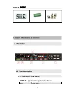
Page 1: ...LVP615U LED HD Video Processor User Manual V1 0 ...

Page 2: ...ote control schematic 13 4 2 Remote control operation instructions 15 Chapter 5 Basic user instructions 5 1 Input signals selection 17 5 2 PIP PBP operation 21 5 3 Mosaic operation 22 5 4 Other basic user operation 23 Chapter 6 Setup menu instructions 6 1 Output image setting 26 6 2 Input video signal setting 30 6 3 Text overlay setting 33 6 4 Image quality setting 35 6 5 Audio setting 36 6 6 Comm...

Page 3: ... Wired network 50 7 1 3 WIFI connection 51 7 2 LVP615U series PC control software instructions 58 7 2 1 Control method 58 7 2 2 Software interface instructions 59 7 3 APP remote control 76 7 3 1 Connection 77 7 3 2 APP control instructions 80 Chapter 8 Copyright information 97 Appendix modify the record table 98 ...

Page 4: ...s are not hot swappable Caution 1 Please thoroughly read this manual before using this device and keep it well for future reference 2 In the event of lighting or when you are not going to use the device for a long time please pull the power plug out of receptacle 3 Nobody other than professional technicians can operate the device unless they have been appropriately trained or under guidance of tec...

Page 5: ... whether all the following things are included in the package If anything is found missing please contact the dealer Standard accessories The accessories supplied with this LED Video Processor may differ from the figures contained in the User s Manual but they are applicable for the regions where you live LED sending card is optional 1 5m power cord 1 1 5m DVI cable 1 0 5m DVI cable 1 1 5m RS232 t...

Page 6: ...LVP615U 使用说明 6 Chapter 3 Hardware connection 3 1 Rear view 1 3 5 2 4 4 3 2 Ports description 3 2 1 Video signal inputs INPUT LVP615U supports 8 video signals input as follows Port Description ...

Page 7: ... The other 2 channels are AD1 AD2 external audio input AD1 and AD2 can be mapped to any one of signal inputs and will be switched synchronous to the selection of video input signals 3 2 3 Video signal output Port Description VGA OUT 1 channel analog RGBHV signal output which can be connected to a local display device for monitoring it is strongly recommended to use this port when operating and set...

Page 8: ...l communication interface used to connect the RS232 port of PC to realize PC software control RS232 LOOP Serial communication cascading output for connecting the RS232 IN of next unit through single PC can control several units RF Antenna interface of wireless control function RF 2 Network intelligent module 3 3 Hardware connection diagram ...

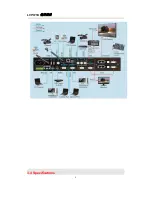
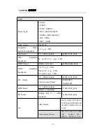
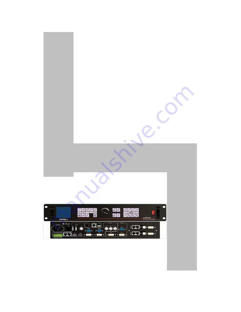
Page 9: ...LVP615U 使用说明 9 3 4 Specifications ...

Page 10: ...bPr format SD HD CEA 861 1920x1080p_60Hz YPbPr Amplitude Impedance Y 1V p_p 75Ω Pb 0 35V p_p 75Ω Pr 0 35V p_p 75Ω DVI format PC VESA standard 2304 1152_60Hz Custom output format Width 3840 Height 1920 HDMI format PC VESA standard 1920 1080_60Hz HDMI1 3 CEA 861 DP format Display Port 1 1 VESA standard 1920 1080_60Hz USB video format MKV TS M2TS TP TRP AVI WMV RM RMVB MPEG M PG MP4 VOB MOV ISO DA T ...

Page 11: ... 1080p_50Hz 60Hz 1366 768_60Hz 1440 900_60Hz 2048 1152_60Hz 2560 816_60Hz 2304 1152_60Hz 1920 1200_60Hz 1200 1600_60Hz 1080 1920_60Hz 1536 1536_60Hz Custom output format maximum horizontal pixel 3840 maximum vertical height 1920 Output connectors VGA OUT 15Pin D sub female DVI OUT1 24 5 DVI_I DVI OUT2 24 1 DVI_D Others Control RS232 USB LAN WIFI Remote control Input voltage 100 240VAC 50 60Hz Powe...

Page 12: ...LVP615U 使用说明 12 3 5 Product dimensions Product Size 483 L x 274 W x 66 6 H mm Weight G W 5 7 Kg N W 4 2Kg ...

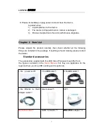
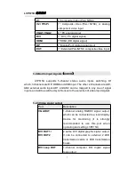
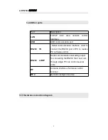
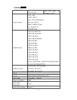
Page 13: ...LVP615U 使用说明 13 RS232 cable order ...

Page 14: ...ns LVP615U supports front panel button remote control RS232 and LAN control Same printing on remote control buttons and front panel buttons same button functions The instructions are as below 4 1 Front panel buttons and remote control schematic 1 2 4 3 5 8 7 6 9 10 11 ...

Page 15: ...A auto adjustment button automatically adjust the VGA input signal 4 1 4 Switching time setup button select seamless switching time including 0 second cut 0 5 second 1 0 second and 1 5 second fade in fade out and blend switching function 5 4 6 The buttons on remote control have the same functions as the relative buttons on front panel 3 9 ...

Page 16: ...ion to choose different group input or current input itself as the PIP signal Switch PIP PBP model 4 1 7 Mosaic button Turn on off mosaic function The indicator shows the current state of mosaic 4 1 8 Freeze button turn on off freeze function 4 1 9 Brightness adjustment button adjust output brightness level under user operation station 4 1 10 remote control sensor built in infrared receiver 4 1 11...

Page 17: ...operation please replace new battery immediately 4 3 3 Batteries shall not be exposed to such as sunlight fire or the like overheated environment Chapter 5 Basic user instructions After LVP615U boot it enters the operation status of last shut down including signal switching status PIP POP or Text overlay status and mosaic status Among them PIP PBP or text overlay status and mosaic status can only ...

Page 18: ...e switching method can be set in user setup menu 2 6 switch mode One key switch is default method One key switch to new input signal through input signal selection buttons Pre Take switch only available for seamless switching Press input buttons to preselect first Then press Take button to switch from current input signal to preselected signal ...

Page 19: ...video PAL NTSC or analog component video input 2 PC analog signal input 1 DVI digital signal input 1 HDMI digital signal input 1 DisplayPort digital signal input 1 extended signal input Note 1 YPbPr and V2 share the same port If need configure the port to YPbPr in setup menu 5 1 1 One key switch LCD screen display as below ...

Page 20: ...t signal The first line on the LCD display the current input signal Like Input HDMI The second line on the LCD display the signal status If no active input display No input Meanwhile the corresponding indicator flicker Led screen is black If active input display input signal format Like 1080p_60Hz 5 1 2 Pre Take switch LCD screen display as below ...

Page 21: ...f switching preselect signal become the current input signal The status of the preselect signal indicator when the signal is valid the indicator flicker rapidly when the signal is invalid the indicator flicker slowly Note Pre Take switch only available for seamless switching LVP615U supports seamless switching between any two different input groups as follow Same group does not support seamless sw...

Page 22: ... support fade in fade out switching Blend switching at this moment on the LCD current input is the main input Select different group input signal as blend signal The main input will overlay in the blend signal Press blend signal or main signal button again Then switch to selected signal The whole process is fade in fade out effect Main Input HDMI Main In Status 1080p_60Hz Blend Input V1 Blend In S...

Page 23: ... PIP PBP mode Then press input signal button to select PIP signal At the same time LCD will display main input and pip input status and size as shown below Main Input HDMI Main In Status 1080p_60Hz PIP Input V1 PIP In Status PAL Main Output Size 1920x1080 Main Output Start 0 0 PIP Output Size 640x320 PIP Output Start 16 16 Select PIP input signal In PIP mode press button to select corresponding si...

Page 24: ...c operation Press the button again and the indicator is off LVP615U exits Mosaic Mosaic Input DVI In Status 1080p_60Hz Input Image Size 960x540 Input Image Start 0 0 Mosaic out size 1920x1080 Mosaic out start 0 0 Mosaic PIP off Device ID 1 入拼接信号 DVI Note 5 3 1 In mosaic mode PIP display is available 5 3 2 In following conditions LVP615U cannot enter mosaic status 1 The input signal selected is not...

Page 25: ...64 0 100 default value is 50 button description BRT Reduce LVP615U output brightness the lowest is 0 BRT Increase LVP615U output brightness the highest is 64 or 100 5 4 2 VGA input auto adjustment Auto When LVP615U is in one key switch status and current valid input signal is VGA press Auto button to adjust VGA input signal sampling parameters Then the VGA output image can be clear and full This o...

Page 26: ...ge is compressed and fully displayed on the led screen and the indicator is off Part Part display the input image is not compressed Only a part of it can be displayed on the screen and the indicator is on Note When the width and height of input image are lower than the LED screen real width or height value Part display is invalid 5 4 4 Text overlay LVP615U allows for overlapping text logo or flash...

Page 27: ...signal switching status press OK to check the LVP615U current setting and information System info model LVP615U version V0 0 8 V0 0 8 IP 192 168 1 8 Mask 255 255 255 0 Gate 192 168 1 1 MAC 76 64 77 00 00 00 Device ID 1 Chapter 6 Setup menu instructions Setup menu is to set the entire processor There are 9 section including output image input image text overlay image quality audio communication lan...

Page 28: ...ance 9 After the system starts Press Setup to enter the setup menu Then press button to select the corresponding menu item to be set Press OK button to enter and return back upper level menu The following is a detailed description of each menu function 6 1 Output image setting Press Setup to enter setup menu Press button to select 1 Out ...

Page 29: ... fixed output format and custom output format refer to page 9specifications Users can select fixed output format not less that the LED screen resolution or select custom output format which can realize pixel to pixel display in concert with 2 1 1 custom DVI EDID Operation steps Press to select 1 1 Resolution item Rotate knob to select suitable output format like 1280 1024_60 Press OK button the sc...

Page 30: ...om output format after selection need further set 1 1 1 custom width 1 1 2 custom height and 1 1 3 custom V frequency Press button to 1 1 4 Apply Press OK to make parameters effective 1 1 Custom Resolution 1 1 1 Cus Width 1920 1 1 2 Cus Height 1002 1 1 3 Cus V Freq 60 1 1 4 Apply OK To Apply ...

Page 31: ...art Out vert height LED screen LVP615U output resolution 1920 1080 LVP615U out image area 1920 1080 As shown in the above picture the size and location of output image of LVP615U can be defined in 4 parameters Item NO Item name 1 2 Out_hori_width 1 3 Out_vert_height 1 4 Out_hori_start 1 5 Out_vert_start Note current set parameters can be changed by rotating knob knob rotating speed can decide the ...

Page 32: ...rn of 36 pcs will be selected Operation steps Press button to select 1 6 Test pattern item then rotate knob to select suitable test pattern number and press OK to apply the test pattern 1 1 Resolution 1920x1080_60 1 2 Out Width 1920 1 3 Out Heith 1080 1 4 Out H_Start 0 1 5 Out V_Start 0 1 6 Test pattern 0 5 Note The current signal must connect valid input Then the test pattern has output Otherwise...

Page 33: ...DID In concert with custom output format LVP615U can realize DVI input image and output image pixel to pixel display LVP615U supports 16 fixed DVI EDID and custom EDID Normally the parameters setting should be consistent with custom output format refer to page28 Operation steps In the menu 2 1 DVI EDID rotate knob to select suitable resolution and press OK to save data After save data need press O...

Page 34: ...image interruption caused by the fault of signal source 2 Input video signal 2 1 DVI EDID 1280x1024_60 2 2 V1 V2 backup off 2 3 VGA1 VGA2 backup off 2 4 HDMI DVI backup off 2 5 V2 or YPbPr V2 2 6 switch mode one key switch As shown in the above table if 2 2 V1 V2 backup on if V1 signal is lost processor will switch to V2 automatically 6 2 3 V2 or YPbPr selection V2 and YPbPr of LVP615U share the s...

Page 35: ... mode Press Setup to enter setup menu press to select 2 Input video signal Then press OK to enter 2 input video signal and press to select signal switch mode one key switch or Pre Take switch Press OK to apply 2 Input video signal 2 1 DVI EDID 1280x1024_60 2 2 V1 V2 backup off 2 3 VGA1 VGA2 backup off 2 4 HDMI DVI backup off 2 5 V2 or YPbPr V2 2 6 switch mode Pre Take SW ...

Page 36: ...e menu 3 1text overlay rotate knob to switch it on Then press to enter 3 2text source menu to rotate Knob to select text input signal Text overlay is on If need turn it off enter 3 1 text overlay and switch it off 6 3 2 Text overlay parameters setting 3 1Text mode LVP615U can custom text mode threshold or threshold threshold means text signal image which is less than the current threshold value wi...

Page 37: ...s is used to set three thresholds subtitles red green and blue respectively for a particular value between 0 to 248 The following is the text overlay example Text file is made by Powerpoint Parameters are as follow Main picture text text overlay 3 3 Text mode threshold 3 4 Threshold R 248 3 5 Threshold G 248 3 6 Threshold B 248 ...

Page 38: ...ut color 50 V1 50 V2 50 HDMI 50 DVI 50 DP 50 EXT 50 V1 50 All 50 4 2 Sharpness normal 4 Color Brightness Default 4 3 Brightness 50 50 LVP615U supports custom color sharpness and brightness setting List as follow Item name Definition 4 1 color Adjustment range 0 100 default 50 ...

Page 39: ...or RGB format DP DVI and HDMI VGA is RGB format So setting is not available 6 5 audio setting 5 Audio 5 1 AD1 Config V1 5 2 AD2 Config V2 LVP615U supports 4 channels of stereo audio input signals Three of them are HDMI and DP audio The other two AD1 and AD2 are external input Audio input signals for AD1 and AD 2 can be configured to match the video input signals correspondingly and switching betwe...

Page 40: ...nication 6 Communication 6 1 IP 192 168 1 8 6 2 mask 255 255 255 0 6 3 gate 192 168 1 1 6 4 Mac 76 64 77 00 00 00 6 5 device ID 1 LVP615U can be remotely controlled via Ethernet Communication setting menu is used to set network parameters including IP address mask gate MAC and number the multiple LVP615U under the same IP The following is the method of operation In the menu of 6 Communication pres...

Page 41: ...nd press OK to save The LCD screen will give tips to restart the system and do according to the prompt 6 7 Language setting LVP615U supports Chinese and English language Rotate knob to select one and press OK to save 7 Language 7 1 语言 Language Chinese ...

Page 42: ...EO 8 4 De Interlace off 8 5 Bright level 0 64 8 6 DVI hotplug off 8 7 Wifi reset OK to apply 8 8 Device reset OK to apply 6 8 1 ADC Calibration 8 1 ADC Calibration is used to calibrate the white balance of analog signals to avoid color cast or extreme darkness problem This function is only available for non ext Input VGA CVBS and ...

Page 43: ...s especially dark images like night scenes LVP615U can adjust 8 2 Bias parameters to adjust The value range is 0 100 In the case dark image information lost adding this value will bring back the lost information and fully display the image on LED display Note to make sure of full gray scale of output image the default value is 50 6 8 3 EXT Input Model The option is used to configure extended modul...

Page 44: ...l Operation is as below Enter 8 5 Bright Level rotate knob to select 0 64 or 0 100 and press OK button to confirm the setup 6 8 6 DVI hotplug DVI hot plug signal is sent by processor to graphic card or other signal source devices as a gist to let the signal source device whether outputs DVI signal source or not A few PC when use some software play video on extended desktop the hot plug signal to t...

Page 45: ...tton there is one information on LCD screen to remind you data will reset Press OK button to apply LVP615U starts to reset 8 Device Reset The menu is used to initialize LVP615U Operation as below Enter 8 8 Device Reset and press OK button there is one information on LCD screen to remind you data will reset Press OK to apply LVP615U will reset and restart ...

Page 46: ...art 16 D 5 MAIN Width 1920 D 6 MAIN height 1080 D 7 MAIN H_Start 0 D 8 MAIN V_Start 0 The setup option is used to set LVP615U s three user defined PIP PBP mode Operation as below When LVP615U s PIP PBP status is open the indicator light on On Off button is lit up press Setup button LVP615U enters D PIP PBP menu Then press ...

Page 47: ... save 0 0 PIP H_start PIP Width PIP V_Start PIP height Main out image LVP615U output resolution 1920 1080 1920 1080 Pip out image Main V_start Main height Main width main H_start 6 10 Mosaic setting E Mosaic Video Wall App E 1 LED Total Width 3840 E 2 LED Total Height 2160 E 3 Unit Width 1920 E 4 Unit Height 1080 E 5 Unit H_Start 0 E 6 Unit V_Start 0 E 7 Sync Mosaic ON E 8 Auto Calculation OK To A...

Page 48: ...rge LED display With frame synchronization technology LVP615U solves the problems of misplacement and delay of output image existing in ultra large LED mosaic being able to provide real time clear and fluent display effects LVP615U supports multiple units cascading splicing By this way smaller pieces of LED screens can be integrated into a large display For example if the output definition of LVP6...

Page 49: ...stment setup menu E Mosaic Return to upper level setup menu under the mode of adjustment setup press button LVP615U exits adjustment setup Note when use multiple LVP615U cascading splicing to make sure the output image have uniformity every unit s parameters of 4 3 brightness 4 1 inpu color 4 2 sharpness and 8 2 bias must be same Operation is as below When the input signal of LVP615U is DVI format...

Page 50: ...g us how to use multi units cascade of LVP615U and what we should pay attention to The definition of the LED screen is 3456 1920 we can divide it into the four small pieces of LED of 1728 960 pixels as shown in figure below each piece of small LED screen is driven by a unit of LVP615U With total 4 sets of LVP615U the 3456 1920 pixels LED screen is able to display a full picture 1 1728 960 2 1728 9...

Page 51: ...op to 3 and 4 After that the output signal of 0 LVP615U is cropped and scale up in 1 LVP615U 2 LVP615U 3 LVP615U and 4 LVP615U Finally the image that they output will be finally displayed as a whole picture on 4 pieces of LED screens The parameters of the 4 units of LVP615U are as below Setup options Parameter setups of processor 1 2 3 4 E 1 LED total width 3456 E 2 LED total height 1920 E 4 Unit ...

Page 52: ...n order to ensure all output images are synchronous to each other please note the following settings 1 The input signals can be only DVI signals and if the processor is in mosaic mode it will be unable to switch input signals 2 All the 5 processors must be set the same output resolution ...

Page 53: ...ntrol terminal Here we instruct the hardware connection and software operation as below 7 1 Hardware communication LVP615U remote control ports include RS232 USB Wired network and Wifi control As below we illustrate hardware communication connection and setup respectively 1 3 4 2 LVP615U Remote communication ports 1 RS232 2 USB 3 LAN 4 WIFI ...

Page 54: ... for remote control When use RS232 control we only need to use an RS232 cable to connect PC to processor s RS232 port then we can use software to remote control processor When PC does not have RS232 port USB control method can be used PC LVP615U RS232 or USB ...

Page 55: ...mmunication LVP615U has been a work station in the local area network So another terminal device in the local area network can control the LVP615U through software As the picture below through software anyone of terminal work station in the local area network can control the LVP615U in the local area network by remote method router Work station2 Network cable Network cable Work station1 LVP615U WI...

Page 56: ...directly and control Second Through WIFI connect wireless Router and become a work station in the local area network so another terminal device in the local area network through software to control LVP615U by remote method the control method is similar through LAN port connecting Here are relative setup and instruction about LVP615U WIFI module and how to realize the 2 control methods NOTICE When ...

Page 57: ...op with wireless network open network and share center search and connect the wireless network named LVP615U the default WIFI password is 88888888 Configuring network be automatically obtain IP address and DNS server address show as the picture below ...

Page 58: ...LVP615U 使用说明 58 Configuring network be automatically obtain IP address and DNS server address show as the picture below ...

Page 59: ...g setup menu 8 7Wifi reset to reset WIFI module refer user manual page 48 then restart and connect 7 1 4 Wireless Module Configuration 1 Running wireless scan configuration software LVP615U WIFI Config Tool exe the application software is as below ...

Page 60: ...LVP615U 使用说明 60 2 Click Scan to search LVP615U in the local area network after searching module the information display as below ...

Page 61: ...ace will display relative information 4 Now you can configure module Configuration options include Mode Setting AP Setting STA Setting Serial Port Parameter Setting Socket Setting and Advanced setup See the configuration method step by step below Notice after configuring every step you need to click save button to save configuration parameter All modified parameters will be valid after module rest...

Page 62: ...Establish a encrypted wireless network similar to a wireless router Mainly used to reset module or control WIFI in the status of no local area network Recommended STA Make the LVP615U as a work station configure and join a wireless network It can be realized by typing in router name and password b AP Setting and STA Setting After selecting the mode we need to configure specific parameters for the ...

Page 63: ...LVP615U 使用说明 63 AP setting ...

Page 64: ...LVP615U 使用说明 64 Click search key to find the around wireless network STA setting Notice Better use manual method instead of automatic method to avoid disconnection due to IP address changes ...

Page 65: ...save button to save change As the picture below shows the boardrate should be 9600 d Socket Setting This step is for Setting basic parameter of Socket Single or Double Socket are supported After setting configuration click Save button to save Please notice that the local port number of Socket A should be same when configuring the PC software ...

Page 66: ... super manage Super manage includes modifying user name and password of module Identification information name and group name of module reset module and reset to default Please set according to needs See the picture below ...

Page 67: ... can realize Selecting input signal switch by seamless switching or fade in fade out mode 3 user defined modes of double picture display or test overlay Turn on or off Bypass Freeze and Mosaic functions Specific parameters of LVP615U setting Timing control function set time for switching or select input signals Multi units cascading splicing function ...

Page 68: ...e control of LVP615U can realize connection by RS232 USB LAN or WIFI After connecting and needed configuration we can run the control software LVP615U Control Software exe 1 Introduction of Software Interface Double click the software the software interface shows as below ...

Page 69: ... Communication Setting 2 Language Setting 3 Signal Switch 4 Function and Mode Selection 5 Information 6 Timing Control Setting 7 Output Parameters Setting Screen Setting 8 Multi Units Cascading Splicing Setting Quick Mosaic 9 Output Resolution Setting 1 Communication Setup ...

Page 70: ...you need to controlled If select network connection firstly must set the network connected being correct the relative setup about wired network prefer 6 Communication user manual page 46 wireless network setup refer user manual page 53 In IP address and port number option type in correct setup the default setup of wired network and wifi AP mode refer the table as below connection Default IP addres...

Page 71: ...t starting up 2 Language setup Software interface displays language selection and the software supports two languages Chinese and English 3 Signal select The buttons of the signal area respectively represent the corresponding keys and status indicators in the panel of the processor After the device is successfully connected the software will read the input signal source you currently selected and ...

Page 72: ... below 4 function and mode setup The buttons in this area used for PIP TEXT Text Overlay BYPASS FREEZE MOSAIC PIP PBP PIP switch used to open or close PIP mode meanwhile the bright point above the button indicates the mode open or not M1 M2 M3 PIP mode buttons the blue bright point above the mode button shows which mode you have selected TEXT text overlay display switch used open or close text ove...

Page 73: ...input signal source of LVP615U as per the preset timer plan The system provides four cycle timer modes i e Day Week Month Once Start timing Start open timing control function Stop timing stop timing control function Timer spread or shrink timing execution list on right side Click Program to enter timer setup menu where you can view the timer plan you already set or add modify delete timer plans ...

Page 74: ...are two types of plan 1 Cycle Plan 2 Once plan Cycle Plan is sub divided into three types 1 Day plan timing in one day 2 Weekly plan timing in one week 3 Monthly plan timing in one month User can select one type he desires The plan items of Day Plan define hours minutes seconds Each week has 7 days so the plan items of Week Plan define week day hour minute second ...

Page 75: ...s The plan items of Once Plan define year date hours minutes seconds Cycle plan and once plan can work together For each type of plan the plan items can be added modified deleted For example the figure below shows how to add plan items to a day Plan Select the plan already added then you can modify or delete it ...

Page 76: ...sor As shown in above figure the button Refresh is used to update the information of currently processing parameters after parameters configuration is finished Any abnormal of parameter will be reminded in info field The setting parameter in interface has zury background indicates the parameter is typing in or aren t saved grey background indicates the parameter has been saved ...

Page 77: ...y The mosaic options are provided to set whether the processor adopts synchronous or non synchronous mosaic mode Input image parameters are used to set the location and size of the images to be captured from input image based on the actual size of the screen Caution input image parameters shall not be configured unless the following conditions are met a The input signal of the processor is DVI b T...

Page 78: ...of background location and size of PIP windows then click Save button to save the parameters in the processor 3 TEXT setup It is used to set the red green and blue threshold values of valid information of the text signals to be captured by the processor also to set whether the text is greater or less than threshold values select appropriate threshold values click Save button to save them in the pr...

Page 79: ...ameters being default value Directly click Normal or Sharp the parameters will be saved Notes the default values of brightness color bias are all 50 Configuring audio This option is used to set AD1 AD2 audio port as the corresponding video input port so as to realize synchronous switching of audio video signals Hot spare setup This option is used to turn on off the hot spare function of the follow...

Page 80: ...setup of each processor through fast mosaic menu In this menu user only need select mosaic mode namely how a large is divided into a number of smaller pieces of LED and the actual pixels of each LED driven by each set of processor the program will automatically calculate the mosaic parameters of each set of processor and save them in the corresponding processor Enter Fast Mosaic Menu after enterin...

Page 81: ...processors must use the same output resolution and make sure it the same with that of input DVI signals 3 The current input source of all processors is DVI signals and make sure the Mosaic function is enabled Mosaic indicator illuminates normally The detail step of mosaic Before performing mosaic setup make sure that each LED display and processor are working well and that each LED display is able...

Page 82: ...smaller LED will be arranged User can also manually enter the number of rows and columns then click OK For the LED of 3648x2016 pixels it should select 2x2 mosaic mode 3 Enter actual parameters of each LED After select mosaic mode the result show column will show the actual LED screen layout input the height and width of each led screen like the following picture 4 Parameters configurations of the...

Page 83: ...alculation may be odd if so it is necessary to set an adjusted value to correct the parameters to be even then you can click Set to save it 5 Parameters configuration of other processors Connect other processors to be set in turn using RS232 cable select device ID select No of corresponding LED following above step 4 the system automatically calculates the parameters of the processor then select M...

Page 84: ...ly If select custom resolution you need to set the width height and frame after configuring click OK to apply the resolution 一 Using APP for remote control LVP615U supports to be controlled by mobile device for example tablet computer and mobile phone User can download the APP and install IOS platform can download and install the APP by link https itunes apple com cn app LVP615U id1129709980 mt 8 ...

Page 85: ...here we illustrate by using router function of LVP615U S wifi module Open wireless LAN switch of IOS device in the network searched out connect the WIFI hot point named LVP615U the default password is 88888888 Then open LVP615U control APP to enter guide interface show as the picture below The last 6 positions of the mane is MAC address ...

Page 86: ...LVP615U 使用说明 86 Click connect If the communication is normal this button s color will change into green from gray Connection button ...

Page 87: ...LVP615U 使用说明 87 If connect unsuccessfully click communication option in adjustment setup to make sure the setup is correct or not ...

Page 88: ...LVP615U 使用说明 88 2 APP Operation ...

Page 89: ...aying as the guide interface above APP has four function areas operation control setting Mosaic setting and information Single click guide interface the corresponding buttons will enter selected function interface We illustrate the four function areas respectively as below 1 Operation and Control ...

Page 90: ...使用说明 90 The main functions of operation control interface include signal switch PIP PBP Text overlay and other functions 1 Signal Selection Switch LVP615U could support one key switch and Preselect Take Switch ...

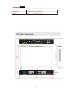
Page 91: ...LVP615U 使用说明 91 ...

Page 92: ... In operation interface click signal switch mode pop the interface as below click to select appropriate switch mode Switching Time Selection In operation interface click switching time popping the interface as below click appropriate switching time ...

Page 93: ...button in signal source selection area to switch signal Preselect Take Switch The switch method s interface as below preselect firstly through signal source button then through TAKE button to switch input signal source blue button indicates current signal green button indicates preselected signal source ...

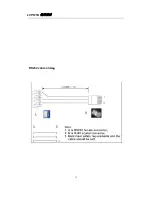
Page 94: ...LVP615U 使用说明 94 ...

Page 95: ...LVP615U 使用说明 95 2 PIP Display ...

Page 96: ...LVP615U 使用说明 96 PIP operation interface as the picture above operation steps Firstly in operation interface click PIP to open PIP function then click PIP ...

Page 97: ...al selection interface through mode button M1 M2 M3 Users could select corresponding display mode Click PIP setting in popping setting interface users can set the location and size of main signal and PIP signal Interface of PIP Signal selection ...

Page 98: ...ion size By multi point touching in the area user could zoom in and zoom out the image by single point touching in the area user could drag and adjust image location 3 Text Overlay Display Text overlay switch The area will be hidden after closing text overlay function Text Overlay Operation Interface is as above operation steps as followings ...

Page 99: ... to open the function then click text signal select relative input signal in popping interface if needy to set the text threshold and other parameters users could click text setting in popping interface Text Signal Selection Interface Text Parameter setting Interface ...

Page 100: ... with the button Mosaic on front panel namely splicing function button AUTO Corresponding with the button AUTO on front panel namely VGA automatic adjustment button 2 Adjustment Setting Main setting functions on adjustment setting interface include output resolution output image parameter input video signal video quality audio communication and language In setting interface clicking corresponding ...

Page 101: ...LVP615U 使用说明 101 1 Output Resolution ...

Page 102: ...ropriate resolution in output resolution menu And click setting the processor will change to new resolution If selecting custom resolution user needs to set the corresponding width height and frame frequency 2 Output Image Parameter ...

Page 103: ... parameter manually then through and to adjust parameters in diagram area of output parameters through multiple point touching to zoom in or zoom out image size single point touching to drag and adjust image location 3 Input video signal User can open input video hot spare and configure V2 YPbPr port ...

Page 104: ...LVP615U 使用说明 104 4 Image quality ...

Page 105: ...LVP615U 使用说明 105 In image quality interface users could set LVP615U output brightness sharpness bias and set every input signal s color independently Reset is used to return to default value ...

Page 106: ...et LVP615U s corresponding input signals of two audio inputs in order to achieve audio and video synchronous switch 6 Network Setting Network setting menu is used to input network parameter of LVP615U this is the premise of remote control 7 Language Setting ...

Page 107: ...plied 3 Mosaic setting Step1 Enter the size of whole screen and the size and location of the processor in use Step2 Open synchronous Mosaic click auto calculation APP will calculate the splicing parameters and apply it automatically Step3 Confirm image Mosaic effect and make some small adjustments on mosaic parameters Mosaic setting interface can achieve quick mosaic parameter setting ...

Page 108: ... be as same as the output resolution of processor 3 Mosaic function is open correctly Operation step described as the picture above 1 Input in relative parameters of actual screen 2 Open synchronization mosaic click automatic mosaic APP calculates the parameters automatically and apply it 3 Confirm image splicing effect if some problem adjust and amend the parameter APP calculated out ...

Page 109: ...LVP615U 使用说明 109 4 Information display The interface includes the APP controllable model APP version information and company information ...

Page 110: ...ALL CO LTD unless with prior consent of VDWALL nobody is permitted to copy or use any part or all of the information contained herein This Manual is provided for reference only VDWALL reserves right to change the product appearance dimensions and specifications from time to time without notice to users ...

Page 111: ...LVP615U 使用说明 111 Appendix modify the record table version time description draft V1 0 2017 5 24 LVP615U first release Lts ...

Page 112: ...LVP615U 使用说明 112 ...

Reviews: