background image

Total solder points: 187 
Difficulty level:  

 beginner

 1

o

  2

þ

 3

o

  4

o


5

o

advanced


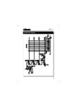
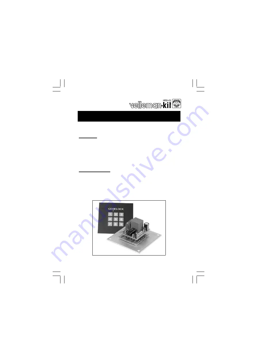
K6400 

Code Lock


ILLUSTRATED ASSEMBLY MANUAL                                                             H6400IP-2 

Features  

 
þ


More than 3000 codes possible. 

þ


State indication by LED. 

þ


Pulse or switch output. 

þ


Nine digits of which 4 code digits. 

þ


Secured against polarity reversal. 


specifications : 


• 

Power supply : 9 to 15VDC or 8 to 12VAC. 

• 

Relay output : 5A / 220V. 

• 

Time limit for code determination : +/- 5sec. 

• 

Current consumption :    Output OFF : 0,3µA 

                                         Output ON  : 40mA 

Summary of Contents for Velleman-Kit K6400

Page 1: ...2 Features More than 3000 codes possible State indication by LED Pulse or switch output Nine digits of which 4 code digits Secured against polarity reversal specifications Power supply 9 to 15VDC or...

Page 2: ...VELLEMAN Components NV Legen Heirweg 33 9890 Gavere Belgium http www velleman be http www velleman kit com...

Page 3: ...nose pliers for bending leads or to hold components in place Small blade and phillips screwdrivers A basic range is f fine For some projects a basic multi meter is required or might be handy 1 2 Assem...

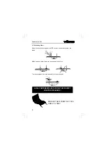
Page 4: ...ace and carefully solder the leads Make sure the solder joints are cone shaped and shiny Trim excess leads as close as possible to the solder joint REMOVE THEM FROM THE TAPE ONE AT A TIME AXIAL COMPON...

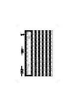
Page 5: ...e Orange Orange Orange Orange Orange Oranje 3 4 Giallo Amarelo Amarillo Keltainen Gul Gul Gul Gelb Yellow Jaune Geel 4 5 Verde Verde Verde Vihre Gr n Gr n Gr nn Gr n Green Vert Groen 5 6 Blu Azul Azul...

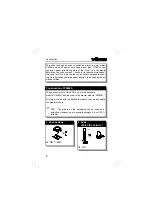
Page 6: ...a standard hous ing Its fully closed operation panel allows it to be used inside as well as outside q SW1 SW9 1 Push buttons SW q LD1 2 Leds Watch the polarity COLOR 2 5 LD CATHODE The unit consist o...

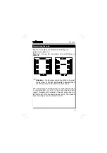
Page 7: ...e code must be as close to the pcb as possible because other wise they will touch the aluminium front panel The code sequence is determined by connecting the lines A respectively B C and D to the conn...

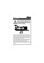
Page 8: ...ated wires at the solder side of the pcb These wires will be used later on for through connection to the master module see fig 2 0 FAttention the wires at the component side must be cut off as close t...

Page 9: ...e input of the code the code lock will only generate a pulse in general this mode is used with door locks closed contact or open contact q NC or NO Fit wire jumper NC if you intend to use the normally...

Page 10: ...q T1 T2 BC547B or eq 5 Transistors q C1 10 F q C2 470 F 7 Electrolytic Capacitors Watch the polarity C Construction q D1 1N4148 or eq q D5 1N4000 q D2 D4 1N4148 or eq FThe side with the mark comes in...

Page 11: ...11 q IC1 CD4066 10 IC Check the position of the notch Construction q J2 2 x 2p 8 Screw connector q RY1 VR15M121C 9 Relay...

Page 12: ...module Take care that the LED is in the front panel Normally neither the LED nor the push buttons may pass through the front panel The push but tons must be flush with the front side Pass a 10mm dista...

Page 13: ...en you can cause the relay to open by entering a digit NOT belonging to the code digits G Tip should the opening time of the relay in the case of the pulse output mode be too short fit a 22 F ca pacit...

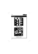
Page 14: ...14 P6400S Keyboard P6400B master PCB layout PCB...

Page 15: ...15 Schematic diagram Diagram...

Page 16: ...ELLEMAN Components NV Legen Heirweg 33 9890 Gavere Belgium Europe http www velleman be http www velleman kit com Modifications and typographical errors reserved Velleman Components nv H6400IP 2001 ED2...

Reviews: