background image


SC-1 Reference Manual 

Firmware Version 2.4F (Full Functionality) 


Summary of Contents for SC-1

Page 1: ...SC 1 Reference Manual Firmware Version 2 4F Full Functionality...

Page 2: ...ITION 10 OPERATING MODES 11 LOWER DISPLAY MODE SELECTION 12 UPPER DISPLAY MODE SELECTION 13 SPEEDOMETER MODE 14 COMPASS MODE 16 TACTICAL COMPASS MODE 19 VMG MODE 23 TIMER MODE 26 START LINE PROXIMITY...

Page 3: ...VING GPS DATA 59 CLEARING GPS DATA 67 UPDATING USER INFORMATION 68 UPDATING DEVICE SETTINGS 69 UPDATING FIRMWARE 72 LAUNCHING GPS ACTION REPLAY FROM CONTROL CENTER 74 MAINTENANCE 75 CONTACT 76 INDEX 7...

Page 4: ...battery life User configurable device settings allow customization of select SC1 functionalities Over 20 hours of GPS data storage at record rate of every 2 seconds Data downloading through a USB lin...

Page 5: ...ER indicator on the upper display Timer mode on the upper display is indicated simply by the presence of a colon between the minutes and seconds Additionally there is no start line proximity mode indi...

Page 6: ...citive touch sensors These touch sensors detect the presence of your thumbs when they are placed on top of the regions shown in the following diagram The captions on the above diagram indicate how the...

Page 7: ...ave less than 5 hours of battery life remaining When the batteries are too low to properly power the GPS chipset the whole display will go blank and flash LO in the lower display Note The above applie...

Page 8: ...the circuit board These markings are circled in red on the following photograph The SC 1 will work with rechargeable nickel metal hydride NiMH batteries or standard disposable AA batteries Disposable...

Page 9: ...k the unit will not allow the user to unlock the buttons Timeout Lock The unit locks when the buttons have been inactive for a time period over the timeout lock value seconds During a timeout lock the...

Page 10: ...eep move your thumb back to the plus button A long beep indicates that you have successfully unlocked the device The unlock indicator will be displayed if the lock feature is enabled All buttons will...

Page 11: ...1 Use your thumbs to cover both the Mode and Minus buttons 2 You will see a countdown starting from 3 on the lower display If you do not see the countdown appear remove and reapply your right thumb 3...

Page 12: ...turn it off use the following procedure 1 Make sure the buttons are unlocked 2 Use your thumbs to cover both the Mode and Minus buttons 3 You will see a countdown starting from 3 on the lower display...

Page 13: ...tellites before it can acquire a GPS solution The data download process normally takes 1 2 minutes or up to 5 minutes if fresh batteries have just been installed The following illustration depicts the...

Page 14: ...ays The mode being displayed is normally made clear by an indicator on the left side of the display There is however no TIMER indicator on the upper display Nonetheless timer information can still be...

Page 15: ...Selection 1 Make sure the buttons are unlocked 2 Put your thumb over the mode button 3 You will hear a beep and see the mode indicator on the lower display change 4 Repeat this procedure to cycle thro...

Page 16: ...pper display In the case of the illustration this is VMG mode 3 Put your thumb over the Up button 4 You will hear a beep and see the indicated mode in the upper display change to match the lower displ...

Page 17: ...he following image shows both the upper and lower displays in speedometer mode showing a speed of 16 9 knots Recalling Maximum Speeds When the lower display is in speedometer mode you can recall your...

Page 18: ...You will see a countdown from 3 to 0 on the lower display 3 When the countdown reaches 0 remove your thumb from both buttons 4 You will see CLr displayed on the lower display This indicates that the...

Page 19: ...egardless of which direction you are actually moving The difference of the SC 1 to a conventional magnetic compass is that the SC 1 measures the direction the device is moving in rather than the direc...

Page 20: ...ts and wind shifts The damping on the SC 1 can be set to 10 different settings d0 d1 d2 d3 d4 d5 d10 d30 d60 and d90 When the damping is set to d0 there is no time averaging and the displayed measurem...

Page 21: ...t your thumb over the Plus button to increase the damping level or over the Minus button to decrease the damping level 3 You will see the lower display scroll through different damping values 4 When y...

Page 22: ...and you start seeing smaller numbers on the tactical compass display you know that you have been lifted regardless of which tack you are on Once you have identified a wind shift using the SC 1 s tact...

Page 23: ...ow Note that in tactical compass the reference wind direction is adjusted to increase or decrease the indicated heading to wind Heading to wind defined as the difference between the boat s current hea...

Page 24: ...6 Adjust your indicated heading to wind to the average of the angles seen in steps 4 and 5 i e split the difference In this example the average would be 45 35 2 40 Once you have done this the referen...

Page 25: ...wind is 40 the same as it was before the wind shift At this point your indicated heading to wind will only be 15 though because the reference wind direction stored on the SC 1 will still be aligned w...

Page 26: ...G upwind and downwind using the method illustrated below Whether you are sailing upwind or downwind the SC 1 breaks your boat s velocity into two perpendicular components One component is perpendicula...

Page 27: ...so you are moving straight downwind 2 Make sure the buttons are unlocked 3 Put your thumb over the plus button and hold it there You will see the display scroll upwards increasing one degree at a time...

Page 28: ...ction in VMG Mode Use the following guidelines to adjust the wind direction programmed on the SC 1 when you are sailing upwind If the indicated VMG seems like it s consistently higher on starboard tac...

Page 29: ...reset to 5 00 at 0 00 The following diagram shows the SC 1 with both the upper and lower displays in timer mode indicating one minute and 36 seconds remaining before the start Note that there is no mo...

Page 30: ...the following procedure to start the countdown 1 Make sure the buttons are unlocked 2 Put your thumb over the minus button 3 The device will beep and the countdown will begin 4 If the lock feature is...

Page 31: ...the Timer 1 Make sure the buttons are unlocked 2 Put your thumb over the plus button 3 Hold the plus button for 2 seconds You will hear a long beep and the timer will reset to the highest sync point y...

Page 32: ...the minus button 3 The timer will jump down to the next lowest sync point you have set in device settings 4 The timer will continue counting normally and the buttons will be automatically locked The...

Page 33: ...odes 30 Incrementing Minutes The timer minutes can be incremented without affecting the timer seconds 1 Make sure the buttons are unlocked 2 Put your thumb over the plus button 3 The timer will jump u...

Page 34: ...ice near the committee boat and another one near the pin An offset that accounts for the distance between the tip of your bow and the location on your boat where the SC 1 is actually mounted can be se...

Page 35: ...ance you are over the line When you are more than 100 meters or boat lengths from the line the display simply shows your distance from the line with no indication of what side of the line you are on W...

Page 36: ...e following procedure to set the committee boat reference point 1 Unlock the buttons 2 Press the Minus button 3 Hold for 3 2 1 4 Release on 0 5 The device will beep and C will be displayed to confirm...

Page 37: ...ollowing procedure to set the pin reference point 1 Make sure the buttons are unlocked 2 Press the Minus button 3 Hold for 3 2 1 4 Release on 0 5 The device will beep and P will be displayed to confir...

Page 38: ...GPS satellites in view and the location of those satellites in the sky Data Logger Mode By turning off all modes you can use the SC 1 strictly as a data logger In this mode the device displays OFF in...

Page 39: ...mmunication with SC 1 Microsoft Net Framework 2 0 Required for Control Center Microsoft Net Framework 3 0 Required for Control Center Java Required for GPS Action Replay The Velocitek installer can be...

Page 40: ...Installing Control Center 37 3 Click Next...

Page 41: ...Installing Control Center 38 4 Once the setup is complete you will get the following message Click Finish...

Page 42: ...rest of the installation will be guided by the Install Shield Wizard If you do not have Java 2 or Net Framework 3 0 the wizard will proceed to install them Click Install Otherwise the wizard will proc...

Page 43: ...Installing Control Center 40 6 Select I accept click Next...

Page 44: ...Installing Control Center 41 7 Select Typical click Next...

Page 45: ...Control Center 42 8 Once Java installation is complete you will get the following message Click Finish 9 If you get the following message do not restart computer to proceed with rest of the installati...

Page 46: ...Installing Control Center 43 10 The wizard will continue with the installation of Net Framework 3 0...

Page 47: ...Installing Control Center 44 11 Once Net Framework 3 0 is installed the wizard will proceed with the installation of Control Center Click Next...

Page 48: ...Installing Control Center 45 12 Enter User Name and Company Name Click Next...

Page 49: ...Installing Control Center 46 13 Select Typical click Next...

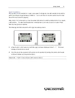
Page 50: ...Installing Control Center 47 14 Click Next 15 Click Continue Anyway...

Page 51: ...Installing Control Center 48 16 Once Control Center is finished installing you will get the following message Click Finish...

Page 52: ...Installing Control Center 49 17 If prompted restart your computer Select Yes click Next...

Page 53: ...level software that allows Control Center to communicate with your GPS device through a USB link Use the following procedure to install the drivers for your Velocitek GPS device 1 Open your device s w...

Page 54: ...Installing Drivers for Your Velocitek Device 51 2 Once the device has been connected to your PC the following window will appear Select the No not this time option and click on Next...

Page 55: ...Installing Drivers for Your Velocitek Device 52 3 Select Install the software automatically and click on Next 4 Select Continue Anyway...

Page 56: ...3 5 Click Finish and you will be taken back to a screen that looks like what you saw in step 3 Repeat steps 3 through 5 to complete the driver installation Congratulations You are now ready to start d...

Page 57: ...ds GPS trackpoints Each trackpoint contains the following information Latitude Longitude Heading Speed Time The SC 1 has room for 17 35 or 70 hours worth of GPS trackpoints at recording rates of 1Hz o...

Page 58: ...Using Control Center 55 Downloading GPS Data Use the following procedure to download GPS data from your SC 1 1 Run Control Center 2 Connect your SC 1 to your PC with the included cable...

Page 59: ...t are shown in the track segment window using the system time zone of the PC The most recently recorded track segments are listed first Select the track segments you wish to download and combine them...

Page 60: ...utton to begin transferring the GPS data from your SC 1 to your computer This process can take as long as 30 seconds for every hour of GPS data stored on the device If the SC 1 s memory is completely...

Page 61: ...d The file names are created with the following format yearmonthday_hourminutesecond For example 080508_083450 corresponds to a track segment where the first trackpoint was recorded at 8 34 50 am on M...

Page 62: ...n only be viewed in a text editor such as Notepad The vcc file format contains a list of times positions speeds and headings The speeds and headings in a vcc file were determined in real time directly...

Page 63: ...Using Control Center 60 Saving GPS Data as a vcc File 1 Download the GPS data you want the file to contain 2 Select File Save...

Page 64: ...Using Control Center 61 3 Give the file a different name from the automatically generated one if you wish Click on the Save button to complete the process...

Page 65: ...ntrol Center 62 Saving GPS Data as a kml or gpx File 1 Download the GPS data you want the file to contain 2 Select File Export and then choose the format you want In the screenshot the kml format was...

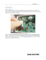
Page 66: ...Using Control Center 63 3 Name the file and click on the Save button to complete the process...

Page 67: ...Using Control Center 64 Converting a vcc File into a gpx or kml File 1 Select File Open and then choose the vcc file you want to convert...

Page 68: ...Using Control Center 65 2 Select File Export and then choose the format you want to convert it to...

Page 69: ...Using Control Center 66 3 Change the name of the converted file optional and click the Save button to complete the process...

Page 70: ...record of your last several days of sailing Since old data is automatically deleted you may never need to clear GPS data from the SC 1 s memory If for any reason you do want to delete GPS data select...

Page 71: ...files created with data from your device Use the following procedure to store user information on the SC 1 1 Select Setup Update User Information 2 The following form will appear Fill out the form and...

Page 72: ...ng with an explanation of each are listed below Compass Declination When defined to the local declination the compass measurement will be referenced to local magnetic north Positive declination repres...

Page 73: ...default Timer Mode Changes To If the top or bottom display is showing the timer it will switch to the mode you choose here when the timer expires You can select from any of the modes The default mode...

Page 74: ...ine proximity is displayed in meters Timeout Lock Enabled Checking the box enables timeout lock When enabled the SC 1 locks when the buttons have been inactive for a time period over the timeout lock...

Page 75: ...ontrol how it operates From time to time Velocitek releases new versions of its GPS device firmware These updates are designed to either improve your device s performance or to tailor its functionalit...

Page 76: ...e hex file you want to install and click Open 3 Wait for the firmware file to be uploaded to your GPS device This will take approximately 10 minutes Progress will be indicated by a horizontal bar grap...

Page 77: ...Using Control Center 74 Launching GPS Action Replay from Control Center 1 Download GPS data or open vcc files in Control Center 2 Click Play with GPS Action Replay...

Page 78: ...is leaves the gasket decompressed and allows it to expand This ensures that it will fit tightly when the enclosure is latched and fully closed If you ever see signs that water is leaking inside the SC...

Page 79: ...1 650 618 2679 Phone Calls will be answered 9AM 6PM Hawaiian Standard Time GMT 10 US and Canada 1 800 693 1610 International 1 650 362 0499 Email support velocitek com Website http www velocitek com...

Page 80: ...intenance 75 Modes Enable 70 O Operating Modes 11 R Recalling Maximum Speeds 14 Resetting Maximum Speeds 15 S Setting Committee Boat End 33 Setting Pin End 34 Signal Acquisition 10 Speed Display In 70...

Page 81: ...Index 78 W Wind Direction in Tactical Compass Mode 20 Wind Direction in VMG Mode 24...

Reviews: