
www.velocitydetection.com Doc: GLT-301-7-3 Issue: 001 Date: 22/06/2021
VL-MH Non Addressable Mini Horn NAC
ELECTRICAL HAZARD:
Disconnect power from equipment
prior
to making any internal adjustments. Service should
only be
performed by qualified personnel.
FRAGILE:
Inspect the equipment prior to installation. Do not
install the equipment if damage is apparent. Do not attempt
to disassemble this equipment. If damaged, return to the
supplier.
ELECTROSTATIC HAZARD:
This is sensitive electronic
equipment. Apply safe ant-static practices when handling
this equipment.
CIRCUIT LIMITATIONS:
The maximum number of detectors
connected to a single detection zone is limited by the control
and indicating equipment, and may be limited by local
regulations.
The non-Addressable Mini Horn is sound alarm notification
appliance which is powered by 2-wired DC 24V and indoor
use only and wall mounted. It has the ability of volume
adjustment function.
The product can be separated from the control panel or
SFM to work independently, when multiple products are
connected to control panel or SFM, the sound between
products in the same circuit area can be synchronized.
When an alarm signal is emitted, it means there may be an
emergency, and should be pay attention immediately.
The Minimum sound pressure is measured in UL reverberant
test chamber.
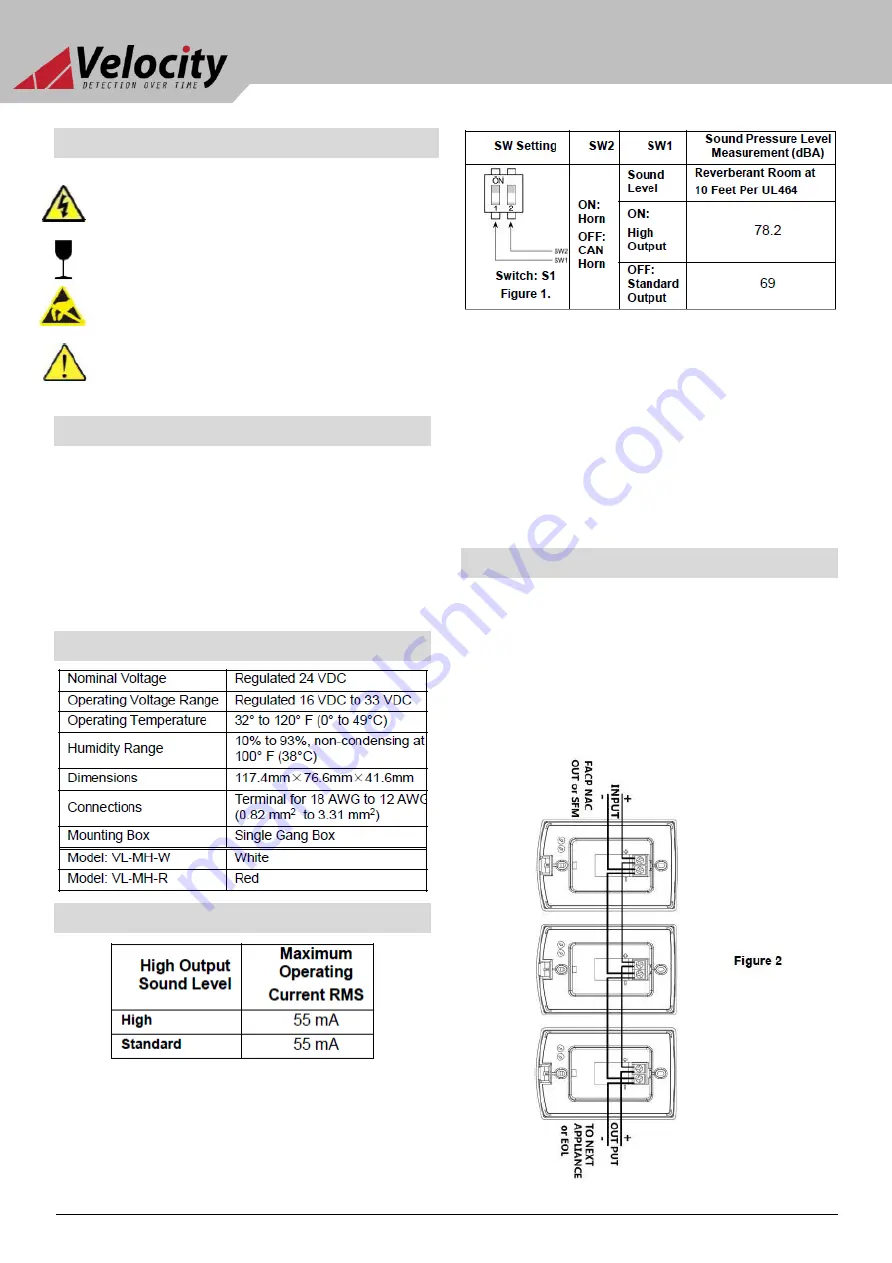
The alarm Tone adjust switch is located in the PCBA of the
product, as shown in Figure1,
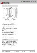
To remove the cover, Depress the snap at the top of the Mini
horn with a flat tip screwdriver while pulling the cover up with
the other hand.
To open the cover, Depress the snap at the top of the
Mini horn with a flat tip screwdriver while pulling the
cover up with the other hand.
Note: Mini Horn will change the tone pattern to Canadian
Broadband Horn if the appliance sw2 set to OFF in FAST
MARCH TIME mode,
In order to ensure that the total current consumption of
the circuit does not exceed the maximum load current of
the FACP or SFM module, the device quantity must be
considered in the design of the loop system.
Number of circuit is connected with the maximum
number of notification products must calculate the loop
line loss of voltage to ensure loop notification products
work in rated voltage range, please refer to the
corresponding FACP or NAC SFM and other equipment
installation instructions.
The wiring circuit is shown in Figure 2
Cautions
General Description
Product Specifications
Sound Level and Electrical Characters
Wiring


