background image


INSTALLATION – OPERATION      & 
MAINTENANCE INSTRUCTION 

HEAT RECOVERY UNITS VHR AND VHR EC MODELS 


VENCO Havalandırma ve Makina San.ve Tic. A.Ş. 

2004. Cad. No:5 45400 OSB Turgutlu 

– MANISA / TURKİYE 

Tel: +90 (236) 332 5070     Fax: +90 (236) 332 5030 

www.venco.com.tr   venco@venco.com.tr 


  2019.10 

Summary of Contents for VHR 04

Page 1: ...NCE INSTRUCTION HEAT RECOVERY UNITS VHR AND VHR EC MODELS VENCO Havalandırma ve Makina San ve Tic A Ş 2004 Cad No 5 45400 OSB Turgutlu MANISA TURKİYE Tel 90 236 332 5070 Fax 90 236 332 5030 www venco com tr venco venco com tr 2019 10 ...

Page 2: ...e 5 1 Lifting Schema 10 Figure 5 2 Installation Schema 11 Figure 5 3 Connection Schema Top View 11 Figure 5 4 Connection Schema 12 6 CONNECTIONS 12 6 1 DUCT CONNECTIONS 12 Figure 6 1 1 Duct Connections Schema Changing the direction of air flow 12 6 2 DRAIN CONNECTIONS 13 6 3 ELECTRICAL CONNECTIONS 13 7 SAFETY REQUIREMENTS 13 8 SAFETY LABELS 14 9 CONTROLS BEFORE START UP 15 10 TRAINING of TECHNICIA...

Page 3: ...AN Electrical Wiring Diagram 26 17 5 APPENDIX 3 Functional Controller FX 3 1 PRO EC FAN Electrical Wiring Diagram 27 17 6 APPENDIX 3 230V 50Hz 1 Phase Electrical Heater Wiring Diagram 28 17 7 APPENDIX 4 400V 50Hz 3 Phase Electrical Heater Wiring Diagram 28 17 8 APPENDIX 5 Electrical Cable And Fuse Selection Tables 29 Table 17 8 1 Heat Recovery Unit Electrical Power Supply and Circuit Breaker Selec...

Page 4: ...n 10 different models VHR 04 07 09 11 16 20 23 29 36 51 High efficiency EC fan devices are classified in 7 different models VHR 04 EC 09 EC 11 EC 16 EC 29 EC 36 EC 51 EC In all models the body is made of galvanized sheet and the cabin is fully insulated for sound and heat insulation The surface of the unit is polished with electrostatic RAL colors All models have two access doors for service to cl...

Page 5: ...Filter Plate Type Heat Recovery Exchanger Figure 2 2 Heat Recovery Unit Schema Figure 2 3 Heat Recovery Unit Schema Plug Fresh Air Fan Direct Driven Drain Pan Exhaust Air Fan Direct Driven Heat Recovery Plate Exchanger Filter Filter Fresh Air Fan Direct Driven Drain Pan Exhaust Air Fan Direct Driven Heat Recovery Plate Exchanger Filter Filter ...

Page 6: ...70 925 1238 1620 2025 2310 2852 3678 4857 Air Flow 150 Pa m h 299 595 790 1045 1320 1790 2045 2370 3137 3750 Efficiency Efficiency up to 70 depending on working conditions ELECTRICAL Voltage 230Volt 50Hz Power Watt 104 204 310 420 450 1030 1030 1100 1 100 1100 SFP 1 15 1 09 1 18 1 27 1 23 2 00 1 76 1 67 1 26 1 41 Air Filter Synthetic Filter For Exhaust and Fresh Air OOPTIONAL Electrical Heater kW ...

Page 7: ...g to EN 13779 VHR Heat Recovery Units are controlled with Standard Electronic Controller SEC supplied as standard with the unit The supply air fan and return air fan are driven as 5 speeds with SEC Also the electrical heater optional can be controlled by SEC manually or automatically depending on the room set temperature has a protection system optional against the frost formation at the temperatu...

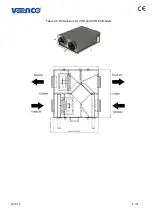
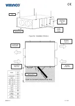
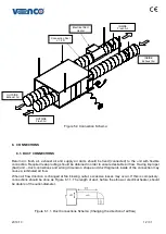
Page 8: ...2019 10 8 31 Table 3 2 Dimensions for VHR and VHR EC Models ...

Page 9: ... Ø200 Ø300 Ø300 Ø300 Ø 355 Ø 400 Ø 450 Weight kg 28 40 40 63 65 76 76 104 145 160 Service Clearance mm Ls 400 450 450 500 550 550 550 450 450 500 MODEL VHR 04 EC VHR 09 EC VHR 11 EC VHR 16 EC VHR 29 EC VHR 36 EC VHR 51 EC Length mm L 800 900 940 1115 1 405 1450 1655 Width mm W 735 860 1020 1030 1115 1100 1265 Height mm H 290 330 445 430 430 595 700 Duct Connection mm Ød Ø160 Ø200 Ø200 Ø300 Ø 355 Ø...

Page 10: ... landing heat recovery units are damaged especially due to wrong methods usage Appropriate lifting methods should be used in order to minimize any possible damage Transpallet or forklift can be used for lifting or transporting small units Lifting and transportation should be done with trained and experienced personnel and security precautions should be taken to prevent the unit to fall over or sli...

Page 11: ...ervice Door Electrical Connection Box OUTDOOR Exhaust Air OUTDOOR Fresh Air INDOOR Fresh Air Model L1 min mm VHR 04 04EC 400 VHR 07 450 VHR 09 09EC 450 VHR 11 11EC 500 VHR 16 16EC 550 VR 20 550 VHR 23 550 VHR 29 VHR 29 EC 450 550 VHR 36 VHR 36 EC 450 600 VHR 51 VHR 51 EC 500 600 INDOOR Exhaust Air Service Zone ...

Page 12: ...dimension shape and duct fragments inside of the connection may cause a turbinated air flow When air flow direction is changed at fan blowing outlet excessive losses may occur If this is compulsory connections should be done as Figure 6 1 1 The length of duct before the elbow or electrical heater should be double of the outlet diameter Figure 6 1 1 Duct Connections Schema Changing the direction of...

Page 13: ... and prepared according to EN 60204 1 Standards The electrical materials cables and all relevant control and remote control equipment should be chosen and designed suitable to unit peculiarities and requirements Electrical wiring diagram is given in Figure 19 1 Appendix 1 7 SAFETY REQUIREMENTS VENCO heat recovery units are produced according to EN 60204 1 Standards and MD 98 37 EC numbered Europea...

Page 14: ... Turn the electrical switch off and wait for the motor blades stop before open the unit Never expose fans cables and connections to the water If the outside temperature is less than 5 C the unit must be stopped and you should contact with VENCO The condense water can be frozen at the temperature less than 5 C it can be damaged to the exchanger Do not operate the unit when the access doors open and...

Page 15: ...r Following points have to be controlled periodically Isolation materials used for heat and sound isolations Cable isolation Control panel Electrical cables and other electromechanical parts Metal and painted surfaces Connection elements such as screw turn screw and joint washer FILTERS Maintenance of the filters should be done regularly Dirty filters can decrease air flow and consequently the cap...

Page 16: ... etc Please make sure that all electrical cables are made according to EN 60204 1 standards and security and protection units belong to all elements Please take out filters after the first operation and clean them properly Then insert the filters in it If all access doors are taken out during the assembly please make sure that service doors are closed Control the adjustment of thermal over load re...

Page 17: ...ation of high pressure Exchanger can be cleaned by using the warm water light detergent After cleaning all plates surface of exchanger should be dried 14 CONTROL FUNCTIONS 14 1 Standard Electronic Controller SEC Figure 14 1 1 Standard Electronic Controller SEC VENCO VHR type heat recovery unit control functions are Unit ON OFF FAN 1 Supply fan Speed control as 5 steps and automatic FAN 2 Exhaust f...

Page 18: ... sensors have to be connected for automatic run of the fans While in fan mode fans don t automatically run If the fans automatically run in different modes when switched to fan mode automatic run is stop Steps manually set with controller Electronical Controller Functions Device ON OFF Stage control of FAN1 fresh air fan OFF 1 2 3 4 5 AUTO Stage control of FAN2 exhaust fan OFF 1 2 3 4 5 AUTO Heat ...

Page 19: ...in the plated heat exchanger fresh air fan will stop and exhaust fan will work at maximum stage for defrosting After defrosting the device will return to its normal working conditions Under these circumstances AL 07 will be shown on screen Commands from the front panel will not run Optionally there is By pass damper control Damper will be automatically ON or OFF position depending on the outdoor a...

Page 20: ...e screen When the heater runs in step two ST 1 2 icon appears on the screen Fresh air fan will run at step 5 for 30 seconds to cool electrical heater Electrical heater will not run when fresh air fan is off Optional air cooler battery only runs in cool mode which runs automatically depends on the room temperature and set point Optional damper runs in heat and cool mode which runs automatically dep...

Page 21: ...FF andalso hh flash press or to adjust hour press mm flash press or to adjust minute The setting method is same for other days 15 TROUBLESHOOTING Table15 1 Troubleshooting Table PROBLEM INDICATIONS POSSIBLE REASON OTHER REASONS and REMEDIES NO AIR FLOW Motor is not working No current No power Check the power supply Thermal protection is open Fan motor cables at the main controller board are not ti...

Page 22: ...2019 10 22 31 Figure 16 1 Heat Recovery Spare Parts Radial Fans Electrical Connection Box Filters Heat Exchanger Control Panel ...

Page 23: ...2019 10 23 31 17 APPENDIX 17 1 APPENDIX 1 Standard Controller SEC Electrical Wiring Diagram ...

Page 24: ...2019 10 24 31 17 2 APPENDIX 2 Functional Controller FEC AC FAN Electrical Wiring Diagram ...

Page 25: ...2019 10 25 31 17 3 APPENDIX 3 Functional Controller FEC EC FAN Electrical Wiring Diagram ...

Page 26: ...2019 10 26 31 17 4 APPENDIX 4 Functional Controller FX 3 1 PRO AC FAN Electrical Wiring Diagram ...

Page 27: ...2019 10 27 31 17 5 APPENDIX 3 Functional Controller FX 3 1 PRO EC FAN Electrical Wiring Diagram ...

Page 28: ...2019 10 28 31 17 6 APPENDIX 3 230V 50Hz 1 Phase Electrical Heater Wiring Diagram 17 7 APPENDIX 4 400V 50Hz 3 Phase Electrical Heater Wiring Diagram ...

Page 29: ...ere VHR 20 1030 Watt 230 volt 50 Hz 6 Ampere VHR 23 1030 Watt 230 volt 50 Hz 6 Ampere VHR 29 1100 Watt 230 volt 50 Hz 10 Ampere VHR 36 1100 Watt 230 volt 50 Hz 10 Ampere VHR 51 1100 Watt 230 volt 50 Hz 10 Ampere MODEL POWER CONSUMPTION ELECTRICAL CONNECTION CIRCUIT BREAKER VHR 04 EC 110 Watt 230 volt 50 Hz 6 Amper VHR 09 EC 340 Watt 230 volt 50 Hz 6 Amper VHR 11 EC 340 Watt 230 volt 50 Hz 6 Amper ...

Page 30: ...5 VHR 07 138 230 VHR 09 87 145 VHR 11 76 126 202 VHR 16 74 123 197 VHR 20 32 53 85 127 VHR 23 32 53 85 127 VHR 29 36 57 86 142 VHR 36 36 57 86 142 VHR 51 26 42 63 104 167 MODEL Cross Section mm 1 5 2 5 4 6 10 16 Cable Length m VHR 04 EC 93 VHR 09 EC 93 156 VHR 11 EC 93 156 VHR 16 EC 57 96 153 VHR 29 EC 96 153 230 VHR 36 EC 96 153 230 VHR 51 EC 60 96 142 238 380 ...

Page 31: ... kW 400 Volt 50 Hz 3 Phase 3 x 16 Ampere VHR 29 29 EC 7 kW 400 Volt 50 Hz 3 Phase 3 x 16 Ampere VHR 36 36 EC 10 kW 400 Volt 50 Hz 3 Phase 3 x 20 Ampere VHR 51 51 EC 12 kW 400 Volt 50 Hz 3 Phase 3 x 20 Ampere The circuit breaker must cut L N at the same time Table 17 8 4 Duct Type Electrical Heater Power Supply Cable Cross Section Table MODEL Cross Section mm 1 5 2 5 4 6 10 16 Cable Length m 3 x mm...

Reviews: