background image

SERVICE MANUAL      

CHASSIS 11  A K 1 9

FIRMEN: EUROLINE

PALLADIUM

S.E.G.
TECHLINE

VESTEL

.

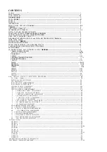
Summary of Contents for 11AK19

Page 1: ...SERVICE MANUAL CHASSIS 11 AK19 FIRMEN EUROLINE PALLADIUM S E G TECHLINE VESTEL...

Page 2: ...9 AK19 CHASSIS MANUAL ADJUSTMENT PROCEDURE 20 For Adjust Settings 20 WHITE BALANCE ADJUSTMENT 20 AGC ADJUSTMENT 20 IF PLL NEGATIVE ADJUSTMENT 20 IF PLL POSITIVE ADJUSTMENT 20 LUMINANCE DELAY ADJUSTMEN...

Page 3: ...nd Blanking 14 Ground Blanking 15 Red input 0 7Vpp 75ohm 15 16 Blanking input 0 0 4VDC 1 3VDC 75ohm 1 6 17 Ground CVS output 17 Ground CVS output 18 Ground CVS input 18 Ground CVS input 19 CVS output...

Page 4: ...e When the horizontal scan is reduced to display 4 3 pictures on a 16 9 picture tube an accurate video blanking can be switched on to obtain well defined edges on the screen Overvoltage conditions can...

Page 5: ...25 082 25 1 175 25to224 25 471 25 to 855 25 2 CABLE CHANNELS CHANNELS S01 to S10 S11 toS39 S40 to S41 FREQUENCY RANGE MHz 69 25 to 168 25 231 25to447 25 455 25 to 463 25 1 Enough margin is available t...

Page 6: ...IF Input Two input pins are provided SIF1 e g for terrestrial TV and SIF2 e g for a satellite tuner The selected signal is passed through an AGC circuit and then digitized by an 8 bit ADC operating at...

Page 7: ...t extra reference circuit The supply voltage is 5VDC at pin 21 1 1 COMBFILTER SAA4961 The SAA 4961 is a one chip PAL NTSC combfilter 1C with internal delay lines filters clock control synchronisation...

Page 8: ...884X is lyC bus controlled single chip TV processor which is intended to be applied in PAL NTSC PAL NTSC and multi standard television receivers These 1C s are nearly pin compatible with the TDA837X T...

Page 9: ...plitude of high reference current 20mA 19 Blue output 2Vpp 20 Green output 2Vpp 21 Red output 2Vpp 22 Beam current limiter input V guard input 23 Red input for insertion 0 7Vpp Max 0 8Vpp 24 Green inp...

Page 10: ...designed to meet a wide range of applications It is a combined VHF UHF tuner suitable for CCIR systems B G H L L I and I The low IF output impedance has been designed for direct drive of a wide varie...

Page 11: ...el 2Vpp Input Current 0 3VMax 1 5V High level 2Vpp Input Current 2Vpp Input Current 2Vpp Input Current 2Vpp Input Current 2Vpp Input Current 4 5Vpp 4 5Vpp 4 5Vpp 4 5Vpp 4 5Vpp 4 5Vpp 1mA Max 3 0V Max...

Page 12: ...ms General Description of TDA2615 The TDA2615 is a dual power amplifier in a 9 lead single in line SIL9 It has been especially designed for mains fed applications Features Requires very few external c...

Page 13: ...00mA Min 50mA Max 500mA 15VDC Max 52V Output current 2App TDA8356 3App TDA8351 Min Vp Max 50V Max 52V Output current 2App TDA8356 3App TDA8351 Max 5 5V lo 100mA Max 52V TDA6107Q The TDA6107Q includes...

Page 14: ...al ground 22 Digital supply voltage 23 Standard select 2 24 Decoupling capacitor 25 Controlling I O pin 26 Analogue ground PLL 27 Analogue supply voltage PLL 28 Internal connected PIN VALUE 200mVpp Mi...

Page 15: ...gulation current ratio Ireg lref 20 5 Min 18 Max 23 2 5VDC Min 2 4VDC Max 2 6VDC SDA525X General description The SDA525X is designed for a low cost mono TV set with analogue picture and sound control...

Page 16: ...42 Clock signal output 43 Data output 44 Local connection 45 SAND input 46 ODD EVEN output 47 OSD red output 48 OSD green output 49 OSD blue output 50 OSD blanking output 51 CORoutput 52 Crystal sele...

Page 17: ...feature extension PINNING 1 NICAM clock output 728kHz 2 Serial NICAM DATA output 728kHz 3 First PC bus slave address modifier 4 SCL PC bus clock 5 SDA PC bus data 6 Analogue supply ground 1 7 Analogue...

Page 18: ...etter than 105 due to gated phase detector at L L accent standard and PLL bandwidth control at negative modulated standards VCO frequency switchable between L and L accent alignment external picture c...

Page 19: ...interface fully lyC bus compatible Byte and Multibyte write up to 8 bytes Page write up to 16 bytes Byte random and sequential read modes Self timed programming cycle PINNING PIN VALUE OV ov ov ov In...

Page 20: ...el 14 Output selector left channel 15 Line output left channel 500mVrms 16 Capacitor timing wideband for dbx 17 Capacitor timing spectral for dbx 18 Capacitor wideband for dbx 19 Capacitor spectral fo...

Page 21: ...y SECAM Enter a SECAM B G colour and black white bar test pattern via RF Adjust Y Delay SECAM till the colour transients on the colour bar of the pattern become as sharper and colours between transien...

Page 22: ...both sides of picture tube as close as possible Check and readjust EW Trapezium item if the adjustment becomes improper after some other geometric adjustments are done 16 9 HORIZONTAL SHIFT ADJUSTMEN...

Page 23: ...na Inb Inc bits Input Source Select Switch This determines which signal is displayed and which is available at CVBSout pin 38 This output can be connected to teletext the TDA8395 SECAM add on or a com...

Page 24: ...1 0 0 Forced Xtal pin 35 PAL NTSC Note d 1 0 1 Forced Xtal pin 35 PAL 1 1 0 Forced Xtal pin 35 NTSC 1 1 1 Forced Xtal pin 35 SECAM Note d In this mode the colour oscillator is forced to use one Xtal...

Page 25: ...d 1 High Gain for Luminance Input When CTI is enabled V27 0 45Vpp B3 Ncin X Vertical Divider Mode 0 Nonnal operation of the vertical divider 1 Vertical divide switched to large search window don tcare...

Page 26: ...f DK 38 0 MHz 1 If DK 38 9 MHz Note2 Ifl 0 Ifl 39 5 MHz Great Britain I Only UHF Tuner 1 Ifl 38 9 MHz Ireland l Standard Tuner Note3 IfM 0 If M N 45 75 MHz S N American Models Tuner UV1336 Only PAL M...

Page 27: ...GENERAL BLOCK DIAGRAM OF CHASSIS AK19 26...

Page 28: ...50V K B CAP CER 820PF 50V K B CAPEL10UF50VM CAPEL10UF50VM CAPEL10UF50VM CAPEL10UF50VM CAPEL10UF50VM CAPEL10UF50VM CAPEL10UF50VM CAPEL10UF50VM CAPEL10UF50VM CAPEL10UP50VM CAPEL10UF50VM POZ NO C373 C37...

Page 29: ...06 L307 L201 L312 L801 L301 L402 L302 L303 L304 L305 L501 L403 L405 L406 L407 L502 L503 L101 L102 L803 L050 L051 LT401 LT301 TR602 TR802 TR601 TR801 L603 SW801 SW501 SW502 SW503 SW504 PL100 PL101 PL12...

Page 30: ......

Page 31: ......

Page 32: ......

Page 33: ......

Page 34: ......

Page 35: ......

Page 36: ......

Page 37: ......

Page 38: ......

Page 39: ......

Page 40: ...SERVICE MANUAL VESTEL 11AK19 MODEL...

Reviews: