background image

rev. 11/1/2016 

  CB-PMPS, manual.doc 

Copyright 2016 Vestil Manufacturing Corp.                                                                                     Page 1 of 23          


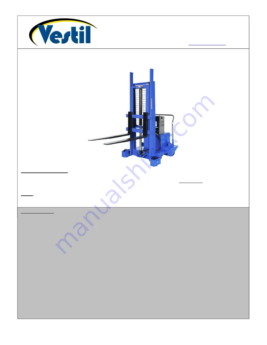
CB-PMPS Series Counterbalanced Pallet Handlers 

Instruction Manual 


Receiving Instructions:


After delivery, IMMEDIATELY remove the packaging from the product. Inspect the product closely to determine 

whether it sustained damage during transport. 

If damage is discovered, immediately


record a complete 

description of the damage on the bill of lading

. If the product is undamaged, discard the packaging.


NOTE:


Compliance with laws, regulations, codes, and non-voluntary standards enforced in the location where the product 

is 

used

 is exclusively the responsibility of the end-user. 


V

ESTIL 

M

ANUFACTURING 

C

ORP

2999 North Wayne Street, P.O. Box 507, Angola, IN 46703 

Telephone: (260) 665-7586  -or-  Toll Free (800) 348-0868 

Fax: (260) 665-1339 

www.vestilmfg.com

    e-mail: 

sales@vestil.com


Table of Contents 

Hazard identification with signal words………………...…………………………………………………………………………........... 2 
Safe Use Recommendations……………………………………………………………………………………………………………… 2 
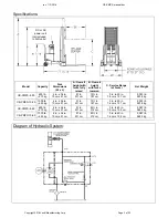
Product specifications by model……………………..……………………………………………………………………………………. 3 
Diagram of Hydraulic System……………………………………………………………………………………………………………… 3 
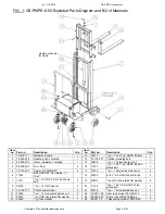
FIG. 1: CB-PMPS-6-50 exploded parts diagram & parts list………………………………………………….................................... 4 
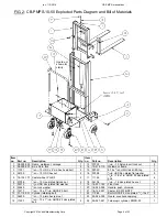
FIG. 2: CB-PMPS-10-50 exploded parts diagram & parts list…………………………………………………………………………. 5 
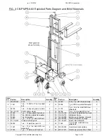
FIG. 3: CB-PMPS-6-60 exploded parts diagram & parts list…………………………………………………………………………… 6 
FIG. 4: CB-PMPS-10-50 exploded parts diagram & parts list…………………………………………………………………………. 7 
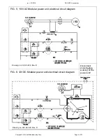
FIG. 5: 115VAC modular power unit electrical circuit diagram……..………………………...……………………………………….. 8 
FIG. 6: 12VDC modular power unit electrical circuit diagram……………………..…………………………………………………... 8 
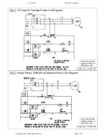
FIG. 7: Three phase AC modular power unit diagram………………………………………………………………………………….. 9 
FIG. 8: Single phase 208 / 230 VAC modular power unit diagram…………………….………………………………………........... 9 
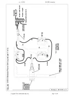
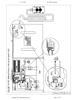
FIGS. 9A & 9B: 12VDC modular power unit layout (parts 1 & 2)………………………..……………………..……………………... 10-11 
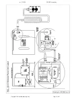
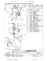
FIG. 10: AC modular power unit layout……………………………………………………………..……………………………………. 12 
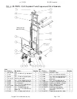
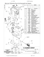
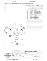
FIGS. 11A & 11B: DC modular power unit exploded parts diagram………………………………………………………………….. 13-14 
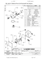
FIGS. 12A & 12B: AC modular power unit exploded parts diagram…………………………………………………………………... 15-16 
Loading Instructions………………………………………………………………………………………………………………………… 17 
Hydraulic system……………………………………………………………………………………………………………………………. 17-18 
DC-Powered hydraulic system troubleshooting guide………………………………………………………………………………….. 18-19 
Battery charger operation………………………………………………………………………………………………………………….. 20 
Inspections & Maintenance……………………………………………………………....................................................................... 21-22 
Labeling diagram…………..……………………………………………………………………………………………………………….. 22 
Limited warranty…………………………………………………………………………………………………………………………….. 23 

Summary of Contents for CB-PMPS Series

Page 1: ...om Table of Contents Hazard identification with signal words 2 Safe Use Recommendations 2 Product specifications by model 3 Diagram of Hydraulic System 3 FIG 1 CB PMPS 6 50 exploded parts diagram part...

Page 2: ...matically void the Limited Warranty see p 23 DO NOT exceed the maximum rated load see Specifications table on p 3 Label 287 on product Inspect the product before each use according to the instructions...

Page 3: ...0 cm x 91 cm 91 in 231 cm 73 in 187 cm 3 in to 50 in 7 6 cm x 127 cm 2 033 lb 923 8 kg CB PMPS 10 50 1000 lb 455 kg 4 in x 36 in 10 cm x 91 cm 91 in 231 cm 73 in 187 cm 3 in to 50 in 7 6 cm x 127 cm 2...

Page 4: ...zinc plated bolt 2 5 16 132 227 Caster 8 3 FWB NTP 2 17 37030 1 2in 13 Nylon insert lock nut 2 6 11365 Bolt HHCS 2 zinc plated 3 4 10x3 18 32030 8 18 x 3 4in HWH tek drill tap 2 7 11211 1 2in 13 UNC x...

Page 5: ...SS zinc plated flat washer 8 5 16 132 173 Caster wheel PH 8 3 2 17 11105 3 8in 16 x 1in HHCS 2 zinc plated bolt 4 6 37039 3 4in 10 zinc plated Nylock nut 2 18 36106 3 8in 16 zinc plated hex nut 4 7 33...

Page 6: ...16 zinc plated hex nut 4 5 37039 3 8in 10 zinc plated Nylock nut 2 17 16 001 190 FL ADJ 810 adjustable floor lock 1 6 33012 1 2in USS zinc plated flat washer 1 18 15 514 112 Weldment frame 1 7 33625 1...

Page 7: ...c plated bolt 4 5 37039 3 8in 10 zinc plated Nylock nut 2 17 36106 3 8in 16 zinc plated hex nut 4 6 33012 1 2in USS zinc plated flat washer 1 18 16 001 190 FL ADJ 810 adjustable floor lock 1 7 33625 1...

Page 8: ...Manufacturing Corp Page 8 of 23 FIG 5 115VAC Modular power unit electrical circuit diagram FIG 6 12VDC Modular power unit electrical circuit diagram Disconnect power before working on the power unit D...

Page 9: ...ng Corp Page 9 of 23 FIG 7 3 Phase AC Modular Power Unit Diagram Disconnect power before working on the power unit Drawing no 99 124 032 FIG 7 Single Phase 208 230VAC Modular Power Unit Diagram Drawin...

Page 10: ...rev 11 1 2016 CB PMPS manual doc Copyright 2016 Vestil Manufacturing Corp Page 10 of 23 FIG 9A 12VDC Modular Power Unit Layout part 1 of 2 Drawing no 99133001 rev A...

Page 11: ...rev 11 1 2016 CB PMPS manual doc Copyright 2016 Vestil Manufacturing Corp Page 11 of 23 FIG 9B 12VDC Modular Power Unit Layout part 2 of 2 Drawing no 99133002 rev A...

Page 12: ...rev 11 1 2016 CB PMPS manual doc Copyright 2016 Vestil Manufacturing Corp Page 12 of 23 FIG 10 AC Modular Power Unit Layout Drawing no 99133003 rev A...

Page 13: ...rev 11 1 2016 CB PMPS manual doc Copyright 2016 Vestil Manufacturing Corp Page 13 of 23 FIG 11A DC Modular Power Unit Exploded Parts Diagram...

Page 14: ...rev 11 1 2016 CB PMPS manual doc Copyright 2016 Vestil Manufacturing Corp Page 14 of 23 FIG 11B DC Modular Power Unit Exploded Parts Diagram...

Page 15: ...rev 11 1 2016 CB PMPS manual doc Copyright 2016 Vestil Manufacturing Corp Page 15 of 23 FIG 12A AC Modular Power Unit Exploded Parts Diagram...

Page 16: ...rev 11 1 2016 CB PMPS manual doc Copyright 2016 Vestil Manufacturing Corp Page 16 of 23 FIG 12B AC Modular Power Unit Exploded Parts Diagram...

Page 17: ...To raise the forks press the UP button on the pushbutton controller This starts the electric motor which turns the hydraulic pump and oil from the reservoir then flows through the suction filter and...

Page 18: ...y voltage Check light b All chassis connections to negative post of battery not made well a Recharge battery b Check and tighten or clean connections if necessary 2 Unit does not raise but motor is ru...

Page 19: ...owly aa Lowering solenoid valve may be incorrectly wired or is stuck open bb Check valve may be stuck open cc Check for leaking hoses fittings pipes dd Cylinder packings may be worn or damaged aa See...

Page 20: ...harger to a damaged extension cord Every DC powered CB PMPS is equipped with an onboard battery charger having a flanged electrical inlet The charger is current limited and will not exceed its rated o...

Page 21: ...damaged hydraulic hoses electrical wires and cords Repair as necessary 5 Carriage rollers see diagrams on p 4 7 check rollers and retaining hardware for normal condition 6 Forks carriage and mast cyc...

Page 22: ...imited Warranty and might make the pallet handler unsafe to use Step 5 Make a dated record of the repairs adjustments and or replacements Label Placement Diagram Each unit should be labeled at all tim...

Page 23: ...y in Angola IN The warranty covers defects in the following original dynamic components motors hydraulic pumps electronic controllers switches and cylinders It also covers defects in original parts th...

Reviews:

Related manuals for CB-PMPS Series