background image


User’s Manual 

EPIA-SN 


Version 1.22 

September 25, 2008 


Summary of Contents for EPIA-SN

Page 1: ...User s Manual EPIA SN Version 1 22 September 25 2008 ...

Page 2: ...ision and other rights owners Use of this copyright protection technology must be authorized by Macrovision and is intended for home and other limited viewing uses only unless otherwise authorized by Macrovision Reverse engineering or disassembly is prohibited Disclaimer No license is granted implied or otherwise under any patent or patent rights of VIA Technologies VIA Technologies makes no warra...

Page 3: ... used in accordance with the instruction manual may cause harmful interference to radio communications Operation of this equipment in a residential area is likely to cause harmful interference in which case the user will be required to correct the interference at his personal expense Notice 1 The changes or modifications not expressly approved by the party responsible for compliance could void the...

Page 4: ...he equipment should be noted 10 Never pour any liquid into the opening Liquid can cause damage or electrical shock 11 If any of the following situations arises get the equipment checked by a service personnel The power cord or plug is damaged Liquid has penetrated into the equipment The equipment has been exposed to moisture The equipment has not work well or you cannot get it work according to Us...

Page 5: ...i BOX CONTENTS One VIA Mini ITX Mainboard One ATA 133 100 66 IDE Ribbon Cable One Driver and Utilities CD One IO Bracket One Quick Installation Guide ...

Page 6: ...Power Supply 10 Back Panel Ports 11 Connectors 13 Jumpers 21 Slots 25 Chapter 3 27 BIOS Setup 27 Entering Setup 28 Control Keys 29 Navigating the BIOS Menus 30 Getting Help 32 Main Menu 33 Main System Overview 35 Advanced Advanced Settings 36 CPU Configuration 38 IDE Configuration 39 Primary IDE Master IDE Slave 41 Super IO Configuration 44 Hardware Health Configuration 45 Hardware Health Configur...

Page 7: ...puting 55 USB Configuration 56 Advanced PCI PnP Settings 58 Boot Settings 60 Boot Settings Configuration 61 Security Settings 63 Advanced Chipset Settings 66 North Bridge VIA CN896 Configuration 67 AGP P2P Bridge Configuration 68 OnChip IGP VGA Configuration 69 South Bridge VIA VT8251 Configuration 71 Exit Options 73 Chapter 4 77 Driver Installation 77 Driver Utilities 78 CD Content 80 ...

Page 8: ...iv This page is intentionally left blank ...

Page 9: ...d VIA EPIA SN uses the Mini ITX mainboard form factor developed by VIA Technologies Inc as part of the company s open industry wide total connectivity initiative The mainboard comes with a VIA Processor boasting of ultra low power consumption cool and quiet operation ...

Page 10: ...slot up to 4 GB Expansion Slot 1 x 16 Lane PCI Express slot Gen 1 1 x 32 bit Mini PCI slot IDE 1 x UltraDMA 133 100 66 IDE port Serial ATA 4 x S ATA II connectors LAN VIA VT6103L 10 100 Mbps Fast Ethernet Controller VIA VT6130 PCI Express Gigabit Ethernet Controller Note System resources such as BIOS PCI etc require physical memory address locations that reduce available memory addresses above 3 G...

Page 11: ...COM 2 5V 12V selectable 1 x LVDS DVI module connector J2 1 x CIR pin connector switchable for KB MS 1 x SIR pin connector IRDA 1 0 1 x CF Compact Flash Type I connector shared with IDE1 1 x Front Panel pin connector 1 x Front panel Audio pin connector for Line out and MIC in 1 x SPDIF out pin connector 1 x Digital I O pin connector 2 x Fan connectors for CPU and System fans 1 x ATX power connector...

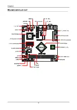
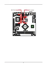
Page 12: ...Chapter 1 4 MAINBOARD LAYOUT ...

Page 13: ...5 ...

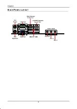
Page 14: ...Chapter 1 6 BACK PANEL LAYOUT ...

Page 15: ...on This chapter provides you with information about hardware installation procedures It is recommended to use a grounded wrist strap before handling computer components Electrostatic discharge ESD can damage some components ...

Page 16: ...nd System Fan CPUFAN and SYSFAN The CPUFAN CPU fan and SYSFAN system fan run on 12V and maintain system cooling When connecting the wire to the connectors always be aware that the red wire positive wire should be connected to the 12V The black wire is Ground and should always be connected to GND CPUFAN Pin Signal 1 FANIO 2 12V 3 GND SYSFAN Pin Signal 1 FANIO 2 12V 3 GND VT8251 CN896 VIA C7 NanoBGA...

Page 17: ...ock a DIMM slot by pressing the retaining clips outward Align a DIMM on the socket such that the notch on the DIMM matches the break on the slot Firmly insert the DIMM into the slot until the retaining clips snap back in place and the DIMM is properly seated Available DDR2 SDRAM Configurations Refer to the table below for available DDR2 SDRAM configurations on the mainboard Slot Module Size Total ...

Page 18: ...mage will be caused ATX 20 Pin Power Connector To connect the power supply make sure the power plug is inserted in the proper orientation and the pins are aligned Then push down the plug firmly into the connector Pin Signal 1 3 3V 2 3 3V 3 GND 4 5V 5 GND 6 5V 7 GND 8 Power Good 9 5V Standby 10 12V 11 3 3V 12 12V 13 GND 14 Power Supply On 15 GND 16 GND 17 GND 18 5V 19 5V 20 5V VT8251 CN896 VIA C7 N...

Page 19: ... Mouse and Keyboard The connector above is for a PS 2 mouse and the one below is for a PS 2 keyboard Serial port COM The 9 pin COM port is for pointing devices or other serial devices VGA Port The 15 pin female VGA connector can be used to connect to any analog VGA monitor ...

Page 20: ...r connecting to external speakers or headphones The Line In jack is for connecting to an external audio device such as a CD player tape player etc The Mic jack is for connecting to a microphone Note The audio ports can be switched to Smart 5 1 6 channel audio output You can enable the function by clicking the Vinyl Audio icon on your desktop after installing the audio driver After completing the p...

Page 21: ...19 GND 20 NC 21 PD_REQ 22 GND 23 PD_IOW 24 GND 25 PD_IOR 26 GND 27 PD_RDY 28 PRIMARY 29 PD_ACK 30 GND 31 PD_IRQ15 32 NC 33 PD_A1 34 IDE_DMADET 35 PD_A0 36 PD_A2 37 PD_CS1 38 PD_CS3 39 HD_LED1 40 GND If two drives are connected to a single cable the jumper on the second drive must be set to slave mode Refer to the drive documentation supplied by the vendor for the jumper settings VT8251 CN896 VIA C...

Page 22: ... VIA C7 NanoBGA2 USB Pin Connector USB The mainboard provides 4 USB pin connectors and one USB pin header allowing up to 2 additional USB2 0 ports Therefore mainboard can support up to 6 USB2 0 ports These ports can be used to connect high speed USB interface peripherals such as USB HDD digital cameras MP3 players printers and modems Pin Signal Pin Signal 1 VUSB4 2 VUSB4 3 USBD_T4 4 USBD_T5 5 USBD...

Page 23: ...ED HD_LED HDD LED shows the activity of a hard disk drive Avoid turning the power off when the HDD LED is still on Connect the HDD LED from the system case to this pin Power Switch PW_BN Connect to a 2 pin power button switch Pressing this button will turn the system power on or off Speaker SPEAK The speaker from the system case is connected to this pin Reset Switch RST_SW The reset switch is used...

Page 24: ..._L 2 AGND 3 MIC2_IN_R 4 GPI 5 LIN2_OUT_R 6 MIC2_JD 7 FRONT_IO_SENSE 8 NC 9 LIN2_OUT_L 10 LIN2_JD LPC Connector JLPC1 This pin connector is for LPC devices Pin Signal Pin Signal 1 LAD1 2 LPCIF_33_CLK 3 PCIRSTX 4 GND 5 LAD0 6 LPCIF_48_CLK 7 LAD2 8 LFRAME 9 SERIRQ 10 LAD3 11 LDRQ1 12 EXTSMI 13 5V 14 3 3V 15 5V 16 3 3V 17 GND 18 GND 19 GND 20 NC F_AUDIO VT8251 CN896 VIA C7 NanoBGA2 10 9 8 6 7 5 4 3 2 ...

Page 25: ... 12V_DIO 3 GPO_1 4 GPI_12 5 GPO_4 6 GPI_13 7 GPO_6 8 GPI_14 9 GPO_7 10 GPI_8 11 GND 12 GND System Management Bus Connector SMBus This pin header allows you to connect SMBus System Management Bus devices Devices communicate with a SMBus host and or other SMBus devices using the SMBus interface Pin Signal 1 SMBCK 2 SMBDT 3 GND ...

Page 26: ...5V 2 NC 3 IRRX 4 GND 5 IRTX KBMS or CIR Connector EXT_KBMS1 The mainboard provides a PS2 pin header to attach a PS2 keyboard and mouse Pin Signal Pin Signal 1 5V 2 GND 3 KB_CLK 4 KB_DATA 5 EXT_KBCLK 6 EXT_KBDATA 7 MS_CLK 8 MS_DATA 9 EXT_MSCLK 10 EXT_MSDATA Note When the pin header is not in use Please short pin 3 5 pin 4 6 pin 7 9 and pin 8 10 VT8251 CN896 VIA C7 NanoBGA2 1 4 3 SIR 5 ...

Page 27: ... 10 Key Digital Audio Connector SPDIF1 This connector is for connecting the Sony Philips Digital Interface S PDIF bracket The S PDIF output provides digital audio to external speakers or compressed AC3 data to an external Dolby Digital Decoder The feature is available only with stereo system that has digital output function Pin Signal 1 5V 2 SPDIF_OOT 3 GND COM2 VT8251 CN896 VIA C7 NanoBGA2 10 9 8...

Page 28: ...d DVI are currently available respectively Pin Signal Pin Signal 1 12V 2 5V 3 12V 4 5V 5 12V 6 5V 7 GND 8 GND 9 3 3V 10 GND 11 3 3V 12 NC 13 NC 14 DVP2D1 15 DVP2D0 16 DVP2D3 17 DVP2D2 18 DVP2D5 19 DVP2D4 20 GND 21 GND 22 DVP2D9 23 DVP2D6 24 DVP2D7 25 DVP2D8 26 DVP2D11 27 DVP2D10 28 GND 29 GND 30 DVP2CLK 31 DVP2DE 32 GND 33 DVP2VS 34 ENVDD 2 35 DVP2HS 36 ENVBLD 2 37 GND 38 PCIRSTX 39 SPD1 40 SPCLK1...

Page 29: ...y power supply To reset the CMOS settings set the jumper on pins 1 and 2 while the system is off Return the jumper to pins 2 and 3 afterwards Setting the jumper while the system is on will damage the mainboard Setting 1 2 3 Normal Operation ON ON OFF Clear CMOS setting OFF ON ON Caution Except when clearing the RTC RAM never remove the cap on CLEAR_CMOS jumper default position Removing the cap wil...

Page 30: ...N OFF Master OFF ON ON Voltage Selector for the CF Connector V_CF_SEL This VCC selector jumper is to determine the input voltage of the CF connector The default value is 3 3V Setting 1 2 3 3 3V ON ON OFF 5V OFF ON ON V_CF_SEL VT8251 CN896 VIA C7 NanoBGA2 2 1 3 2 1 3 3 3V 5V MS_CF_SEL VT8251 CN896 VIA C7 NanoBGA2 2 1 3 2 1 3 Slave Master ...

Page 31: ...OMV2 This VCC selector is to determine the input voltage of each COM connector Setting 1 2 3 5V ON ON OFF 12V OFF ON ON ROM Write Protection WP This jumper allows you to protect from flashing the BIOS ROM Write Protection setting pin1 WP pin2 GND short 1 2 ...

Page 32: ...h connector This is not a default function supported by BIOS Pin Signal 1 INTRUDER 2 GND Wireless LED1 JWLESS LED1 This pin connector is for the LED indicator of VIA VT6656 wireless LAN USB module Pin Signal 1 3 3V 2 W_LESS_LED JWLESS LED1 VT8251 CN896 VIA C7 NanoBGA2 1 2 ...

Page 33: ...ds Read the documentation for the expansion card to see if any changes to the system are necessary PCI Interrupt Request Routing The IRQ interrupt request line are hardware lines over which devices can send interrupt signals to the microprocessor The PCI LAN IRQ pins are typically connected to the PCI bus INT A INT D pins as follows Order 1 Order 2 Order 3 Order 4 MiniPCI Slot INT B INT C INT D IN...

Page 34: ...ive 50 pin Type I adapter PCI Express PCIe x16 The PCI Express slot allows you to insert a PCI Express x16 graphics expansion card First unplug the power supply before adding or removing expansion cards Read the documentation for the expansion card to see if any changes to the system are necessary ...

Page 35: ...27 CHAPTER 3 BIOS Setup This chapter gives a detailed explanation of the BIOS setup functions ...

Page 36: ... 28 ENTERING SETUP Power on the computer and press Delete during the beginning of the boot sequence to enter the BIOS setup menu If you missed the BIOS setup entry point you may restart the system and try again ...

Page 37: ...it from sub menu And discard changes and exit setup Tab Select the item or field Increase the numeric value or make changes Decrease the numeric value or make changes F1 General help only for Status Page Setup Menu and Option Page Setup Menu F8 Load the default CMOS value from Fail Safe default table F7 Discard all changes F9 Load Optimized defaults F10 Save all the configuration changes and exit ...

Page 38: ...E BIOS MENUS The main menu displays all the BIOS setup categories Use the Left Right and Up Down arrow keys to select any item or sub menu Description of the selected highlighted category is displayed at the bottom of the screen ...

Page 39: ...BIOS Setup 31 An arrow symbol next to a field indicates that a sub menu is available see figure below Press Enter to display the sub menu To exit the sub menu press Esc ...

Page 40: ...rogram provides a General Help screen You can display this screen from any menu sub menu by pressing F1 The help screen displays the keys for using and navigating the BIOS setup Press Esc to exit from sub menu and discard changes and exit setup ...

Page 41: ...xit v02 61 C Copyright 1985 2006 American Megatrends Inc F10 F1 Version 001 TEST Build Date 08 08 07 ID 1ADTQ001 Processor VIA C7 Processor 1000MHz Speed 1000MHz Count 1 Select Field Tab System Memory Size 256MB System Memory 16 22 03 System Date Wed 08 08 2007 Main System Overview Use this menu to set basic system configurations Advanced Advanced Settings Use this menu to configure your system an...

Page 42: ...Chipset Settings Use this menu to set specific chipset feature and optimize system performance Exit Exit Options Use this menu option to load BIOS default setting save BIOS setting changes discard BIOS setting changes and exit setup ...

Page 43: ... American Megatrends Inc F10 F1 Version 001 TEST Build Date 08 08 07 ID 1ADTQ001 Processor VIA C7 Processor 1000MHz Speed 1000MHz Count 1 Select Field Tab System Memory Size 256MB System Memory 16 22 03 System Date Fri 08 08 2007 AMIBIOS Show the BIOS version build date and ID Processor Show the total number type speed of VIA processor used in the system System Memory Total memory size used in the...

Page 44: ...ion Super IO Configuration Hardware Health Configuration ACPI Configuration APM Configuration PCI Express Configuration Remote Access Configuration Trusted Computing USB Configuration CPU Configuration Configure the processor IDE Configuration Configure the IDE Integrated Drive Electronics devices Super IO Configuration Configure Super IO chipset Hardware Health Configuration Configure monitor the...

Page 45: ...OS Setup 37 Remote Access Configuration Configure Remote Access Trusted Computing Configure settings related to Trusted Computing innovations USB Configuration Configure USB Universal Serial Bus supports ...

Page 46: ...gatrends Inc F10 F1 VIA C7 Processor 1000 MHz Frequency 1 00 GHz FSB Speed 400 MHz Cache L1 128 KB Cache L2 128 KB Ratio Actual Value 10 CMPXCHG8B instruction support Enabled Items Description Manufacturer The name of company manufacturer VIA Technologies Inc VIA C7 Processor 1000MHz Type of Processor used VIA C7 1GHz Frequency Processor speed 1GHz FSB Speed Front Side Bus speed 400MHz Cache L1 Pr...

Page 47: ...80 Pin Cable Detection Host Options IDE RAID AHCI SATA Controller Controls the features of the Serial ATA controller within the South Bridge Serial ATA is the latest generation of the ATA interface Serial ATA hard drives deliver transfer speeds of up to 300MB sec Setting Description IDE Supports two PATA hard disk drives Disables RAID and AHCI function RAID Only SATA supports RAID and AHCI functio...

Page 48: ...35 Note Set it to default value 0 if you are not using old IDE devices ATA PI 80 Pin Cable Detection This feature allows the IDE controller and IDE device to detect the type of IDE cable that is being used Setting Description Host Device IDE controller and IDE device will detect the types of IDE cable used Host IDE controller will detect the types of IDE cable used Device IDE device will detect th...

Page 49: ...he type of Primary Master IDE drive connected to the system Select Auto to detect IDE drives automatically Settings Not Installed Auto CD DVD ARMD LBA Large Mode This setting allows to disable or enable Auto the LBA capacity Setting Description Disabled Disables LBA Mode Auto Enables LBA Mode if the device supports it and the device is not already formatted with LBA Mode disabled Block Multi Secto...

Page 50: ...e maximum supported PIO mode DMA Mode This setting use to select the Direct Memory Access DMA mode Setting Description Auto Auto detect SWDMAn SingleWordDMAn MWDMAn MultiWordDMAn UDMan UltraDMAn S M A R T This feature enables or disables the Self Monitoring Analysis and Reporting Technology S M A R T The S M A R T technology main function is to monitor the storage devices hard disk drives health a...

Page 51: ...up 43 32 Bit Data Transfer Enabling this setting allows for 32 bit data transfers between the processor and the PCI bus Settings Disabled Enabled Note Recommend set to Enabled to increase of system performance ...

Page 52: ... Port2 IRQ 3 WATCH DOG Disabled Configure SCH3112 Super I O Chipset Items Description Serial Port 1 Address Sets the base I O port 1 address for the onboard serial port Settings Disabled 3F8 3E8 2E8 Serial Port 1 IRQ Sets the base I O port 1 IRQ for the onboard serial port Settings 3 4 10 11 Serial Port 2 Address Sets the base I O port 2 address for the onboard serial port Settings 2F8 3E8 2E8 Ser...

Page 53: ...monitored hardware devices components such as CPU voltages temperatures and fan speeds Items Description H W Health Function Enables Hardware Health Monitoring Device Settings Disabled Enabled PWM 1 Mode Setting PWM Configuration Mode Setting Settings Auto Fan Mode Fan Always On Full Fan Disable Mode fan Manually Mode PWM 1 Ramp Rate If enable limits the amount of change in the PWM duty cycle over...

Page 54: ...5 2006 American Megatrends Inc F10 F1 Enter Advanced ACPI Configuration Chipset Configuration General ACPI Configuration General Advanced Configuration and Power Interface ACPI configuration setting and power management Advanced ACPI Configuration Advanced configuration setting Use this section to configure additional ACPI option Chipset Configuration Chipset Advanced Configuration and Power Inter...

Page 55: ...end Setting Description S1 POS S1 Power On Suspend POS is a low power state In this state no system context CPU or chipset is lost and hardware maintains all system contexts S3 STR S3 Suspend To RAM STR is a power down state In this state power is supplied only to essential components such as main memory and wakeup capable devices The system context is saved to main memory and context is restored ...

Page 56: ...6 American Megatrends Inc F10 F1 ACPI APIC support Enabled AMI OEMB table Enabled Headless mode Disabled ACPI Version Features Enable RSDP pointers to 64 bit Fixed System Description Tables Settings ACPI v1 0 ACPI v2 0 ACPI v3 0 ACPI APIC Features Include ACPI APIC table pointer to RSDT pointer list Settings Disabled Enabled AMI OEMB Table Include OEMB table pointer to R X SDT pointer lists Settin...

Page 57: ...Select Screen Change Option ESC Save and Exit General Help Disabled BIOS SETUP UTILITY Advanced USB Device Wakeup Function Enabled v02 61 C Copyright 1985 2006 American Megatrends Inc F10 F1 Enabled Options USB Device Wakeup Function Settings Disabled Enabled ...

Page 58: ... Disk Power Down Mode Suspend Display Activity Ignore Advanced Monitor Events Controls Monitor IRQ3 Monitor Monitor IRQ5 Ignore Monitor IRQ4 Ignore Monitor IRQ7 Ignore Monitor IRQ10 Ignore Monitor IRQ9 Ignore Monitor IRQ11 Ignore Monitor IRQ14 Monitor Monitor IRQ13 Ignore Monitor IRQ15 Ignore Resume On Ring Disabled Advanced Resume Events Controls Resume On LAN Disabled Resume On KBC Disabled Resu...

Page 59: ...ode Settings Disabled Standby Suspend Hard Disk Power Down Mode Settings Disabled Standby Suspend Advanced Monitor Events Controls Items Description Display Activity Settings Ignore Monitor Monitor IRQ3 Settings Ignore Monitor Monitor IRQ4 Settings Ignore Monitor Monitor IRQ5 Settings Ignore Monitor Monitor IRQ7 Settings Ignore Monitor Monitor IRQ9 Settings Ignore Monitor Monitor IRQ10 Settings Ig...

Page 60: ...ing Settings Disabled Enabled Resume On LAN Settings Disabled Enabled Resume On PME Settings Disabled Enabled Resume On KBC Settings Disabled S3 S3 S4 S5 Wake Up Key Settings Any Key Resume On PS 2 Mouse Settings Disabled Enabled Resume On RTC Alarm Settings Disabled Enabled ...

Page 61: ...BIOS Setup 53 PCI EXPRESS CONFIGURATION Activate State Power Management Enable Disable PCI Express L0s and L1 link power states Settings Disabled Enabled ...

Page 62: ...Save and Exit General Help Select Remote Access type BIOS SETUP UTILITY Advanced Configure Remote Access type and parameters Remote Access Disabled v02 61 C Copyright 1985 2006 American Megatrends Inc F10 F1 Remote Access Configure Remote Access type and parameters Settings Disabled Enabled ...

Page 63: ...Select Screen Change Option ESC Save and Exit General Help Enable Disable TPM TCG TPM 1 1 1 2 BIOS SETUP UTILITY Advanced Trusted Computing TCG TPM SUPPORT No v02 61 C Copyright 1985 2006 American Megatrends Inc F10 F1 TCG TPM Support Settings No Yes ...

Page 64: ...y USB Support Enabled Port 64 60 Emulation Disabled USB 2 0 Controller Mode HiSpeed BIOS EHCI Hand Off Enabled USB 1 1 Ports Configuration Enables 1 1 USB host controller Settings Disabled USB 2 Ports USB 4 Ports USB 6 Ports USB 2 0 Ports Enable Enable or disable Universal Serial Bus 2 0 Settings Disabled Enabled Legacy USB Support This features allows the support of legacy USB devices such as mou...

Page 65: ...h 64h Enabled Not emulate I O ports 60h 64h USB 2 0 Controller Mode Auto decide USB device operation mode Setting Description FullSpeed All of USB Device operated on full speed mode HiSpeed If USB device was high speed device then it operated on high speed mode If USB device was full low speed device then it operated on full speed mode BIOS EHCI Hand Off Settings Disabled Enabled ...

Page 66: ...A IDE Card Auto IRQ3 Available IRQ4 Available IRQ5 Available IRQ7 Available IRQ9 Available IRQ10 Available IRQ11 Available IRQ14 Available IRQ15 Available DMA Channel 0 Available DMA Channel 1 Available DMA Channel 3 Available DMA Channel 5 Available DMA Channel 6 Available DMA Channel 7 Available Reserved Memory Size Disabled Caution Setting a wrong value in section below may cause system malfunc...

Page 67: ...iption Disabled Does not use PCI busmastering Enabled BIOS uses PCI busmastering for reading writing to IDE drives OffBoard PCI ISA IDE Card Set to the PCI slot number that is holding the card Settings Auto PCI Slot1 PCI Slot2 PCI Slot3 PCI Slot4 PCI Slot4 PCI Slots5 PCI Slots6 IRQ3 IRQ4 IRQ5 IRQ7 IRQ9 IRQ10 IRQ11 IRQ14 IRQ15 Setting Description Available Specified IRQ is available to be use by PC...

Page 68: ...nd Exit General Help Configure Settings during System Boot Boot Settings Configuration BIOS SETUP UTILITY Main Advanced PCIPnP Boot Boot Settings Security Chipset Exit v02 61 C Copyright 1985 2006 American Megatrends Inc F10 F1 Boot Settings Configuration Configure settings during System Boot ...

Page 69: ...Mode Force BIOS PS 2 Mouse Support Auto Wait For F1 If Error Enabled Hit DEL Message Display Enabled Interrupt 19 Capture Disabled Quick Boot This setting allows the BIOS to skip certain tests while booting This will decrease the time needed to boot the system Settings Disabled Enabled Quiet Boot Allows the BIOS to show or hide the normal POST messages Setting Description Disabled Displays normal ...

Page 70: ...isabled When an error detected the BIOS will stop the boot sequence Enabled Even an error is detected the BIOS will not stop the boot sequence Hit DEL Message Display Press DEL to run Setup in POST Settings Disabled Enabled Interrupt 19 Capture Setting Description Disabled Will not be able to trap Interrupt 19 Enabled Allows option ROM BIOS to trap Interrupt 19 during boot process ...

Page 71: ...ange the password Supervisor Password Not Installed BIOS SETUP UTILITY Main Advanced PCIPnP Boot Security Settings Security Chipset Exit v02 61 C Copyright 1985 2006 American Megatrends Inc F10 F1 Enter User Password Not Installed Change Supervisor Password Change User Password Boot Sector Virus Protection Disabled ...

Page 72: ...alled Change Supervisor Password Change User Password Boot Sector Virus Protection Disabled Enter New Password Change User Password Install or Change the password Select Item Exit Select Screen Change ESC Save and Exit General Help Install or Change the password Supervisor Password Not Installed BIOS SETUP UTILITY Main Advanced PCIPnP Boot Security Settings Security Chipset Exit v02 61 C Copyright...

Page 73: ...ht characters in length and press Enter The password typed now will clear any previously set password from CMOS memory The new password will need to be reentered to be confirmed To cancel the process press Esc To disable the password press Enter when prompted to enter a new password A message will show up to confirm disabling the password To cancel the process press Esc Additionally when a passwor...

Page 74: ...tem to malfunction BIOS SETUP UTILITY Main Advanced PCIPnP Boot Advanced Chipset Settings Security Chipset Exit v02 61 C Copyright 1985 2006 American Megatrends Inc F10 F1 Enter North Bridge VIA CN896 Configuration South Bridge VIA VT8251 Configuration North Bridge VIA CN896 Configuration Options for VIA CN896 North Bridge South Bridge VIA VT8251 Configuration Options for VIA VT8251 South Bridge ...

Page 75: ...tion Top Performance Disabled GFX PCIE VGA Co Exist Disabled DBI Function Enabled Options Disabled Enabled Caution Setting a wrong value in section below may cause system malfunction Top Performance Settings Disabled Enabled GFX PCIE VGA Co Exist Settings Disabled Enabled DBI Function Setting Description Disabled Use DBI Dynamic Bus Inversion scheme Enabled Does not use the DBI Dynamic Bus Inversi...

Page 76: ... Primary Graphics Adapter This setting allows to select whether to boot the system using the PCI Express graphics card AGP graphics card or the PCI graphics card Settings PCI PCIE AGP AGP PCIE PCI PCIE AGP PCI AGP Aperture Size This setting controls how much memory space can be allocated to AGP for video purposes The aperture is a portion of the PCI memory address range dedicated to graphics memor...

Page 77: ... Share Memory Frame Buffer This setting allows you to select the amount of system memory that is allocated to the integrated graphics processor Settings 64MB 128MB 256MB CPU Direct Access Frame Buffer This setting allows you to control the CPU access to the section of system memory use by integrated graphics processor Settings Disabled Enabled Select Display Device This setting refers to the type ...

Page 78: ...Chapter 3 70 Output Port Settings DI0 DI1 Dithering Setting Description Disabled Image displayed on LCD will not dither Enabled Image displayed on LCD will dither ...

Page 79: ...d LAN PME Disabled PCI Delay Transaction Enabled HDAC Audio Controller Auto Giga LAN Option ROM Disabled 10 100 LAN Controller This setting allows to enable or disable the onboard 10 100 LAN controller Settings Disabled Enabled 10 100 LAN Option ROM Decide whether to invoke the boot ROM of the onboard 10 100 LAN chip Settings Disabled Enabled Giga LAN Option ROM Decide whether to invoke the boot R...

Page 80: ...board VIA High Definition Audio Codec VT1708A controller will be enabled otherwise it is disabled Disable the controller if another controller card is being used to connect to an audio device Setting Description Auto Enables onboard controller if audio device is detected Disabled Turn off onboard controller to allow external controller ...

Page 81: ... 73 EXIT OPTIONS Save Changes and Exit Exit system setup after saving the changes Select Ok and press Enter to save any changes made and exit the program Select Cancel and press Enter will cancel the exit request ...

Page 82: ...hanges Select Ok and press Enter to discards any changes and exit the program Select Cancel and press Enter will cancel the discard exit request Discard Changes Select Ok and press Enter to discards any changes Select Cancel and press Enter will cancel the discard exit request ...

Page 83: ...timized BIOS settings The default optimized values are set by the mainboard manufacturer to provide a stable system with optimized performance Select Ok and press Enter to load the defaults optimal BIOS values Select Cancel and press Enter will cancel the load optimal defaults request ...

Page 84: ...t Exit v02 61 C Copyright 1985 2006 American Megatrends Inc F10 F1 Enter Discard Changes and Exit Discard Changes Load Optimal Defaults Load Failsafe Defaults Load Failsafe Defaults Ok Cancel This option is for restoring all the default fail safe BIOS settings These values are set by the mainboard manufacturer to provide a stable system with basic performance Select Ok and press Enter to loads the...

Page 85: ...rief descriptions of each mainboard driver and application You must install the VIA chipset drivers first before installing other drivers such as audio or VGA drivers The applications will only function correctly if the necessary drivers are already installed ...

Page 86: ...s the driver utilities and software for enhancing the performance of the mainboard If the CD is missing from the retail box please contact the local dealer for the CD Note The driver utilities and software are updated from time to time The latest updated versions are available at http www viaembedded com ...

Page 87: ...The CD should run automatically after closing the CD ROM or DVD ROM drive The driver utilities and software menu screen should then appear on the screen If the CD does not run automatically click on the Start button and select Run Then type D Setup exe Note D might not be the drive letter of the CD ROM DVD ROM in your system ...

Page 88: ...roviding fast graphical access IRQ Routing Miniport Driver sets the system s PCI IRQ routing sequence and VIA INF Driver enables the VIA Power Management function VIA Graphics Driver Enhances the onboard VIA graphic chip VIA Audio Driver Enhances the onboard VIA audio chip VIA USB 2 0 Driver Enhances VIA USB 2 0 ports VIA LAN Driver Enhances the onboard VIA VT6103L 10 100M LAN chip VIA GigaLAN Dri...

Reviews: