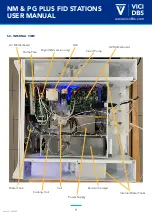
background image

1

NM & PG PLUS FID STATIONS

USER MANUAL

Version 1.03.0000

www.vicidbs.com

TECH SUPPORT

Europe, Asia, Africa, Australia & New Zealand:

techsupport@vicidbs.com

USA, Canada, Central & South America:

techsupportusa@vicidbs.com

Italy

service@vicidbs.com 

VICI AG INTERNATIONAL

Parkstrasse 2

CH-6214 Schenkon

Switzerland
tel:  +41 41 925-6200

fax:  +41 41 925-6201

web: www.vicidbs.com
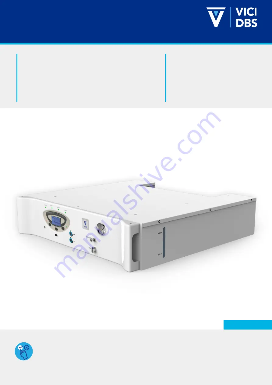
APPLICABLE MODELS

This manual is applicable to the following models:
•  NM Plus 100 FID Station 

•  NM Plus 300 FID Station 

•  NM Plus 600 FID Station

•  NM Plus 1000 FID Station

•  PG Plus 100 FID Station

•  PG Plus 250 FID Station

Version 1.03.0000

Summary of Contents for NM PLUS

Page 1: ...usa vicidbs com Italy service vicidbs com VICI AG INTERNATIONAL Parkstrasse 2 CH 6214 Schenkon Switzerland tel 41 41 925 6200 fax 41 41 925 6201 web www vicidbs com APPLICABLE MODELS This manual is applicable to the following models NM Plus 100 FID Station NM Plus 300 FID Station NM Plus 600 FID Station NM Plus 1000 FID Station PG Plus 100 FID Station PG Plus 250 FID Station Version 1 03 0000 ...

Page 2: ... 7 TRANSPORT AND STORAGE 15 5 8 FUSES AND VOLTAGE SETTINGS 16 6 INSTALLATION AND INITIAL START UP 17 6 1 RECEIVING THE GENERATOR 17 6 2 INSTALLING THE GENERATOR 17 6 3 GAS CONNECTIONS 18 6 4 FILLING THE WATER TANK 19 6 5 INSTALLING THE DEIONIZER BAG 20 6 6 STARTING THE HYDROGEN GENERATOR 21 6 7 TURNING OFF THE GENERATOR 22 6 8 STARTING THE ZERO AIR GENERATOR 22 8 OPERATION HYDROGEN PART 24 8 1 LCD...

Page 3: ... CONNECT POWER AND START UNIT 29 9 2 WARMING UP 29 9 3 SHUTDOWN PROCEDURE 30 10 ERROR LIST TROUBLESHOOTING 30 10 1 HYDROGEN PART 30 10 2 ZERO AIR PART 31 10 2 1 Front Panel LED 31 10 2 2 Error Codes on Mainboard 32 11 MAINTENANCE 33 11 1 ROUTINE MAINTENANCE HYDROGEN PART 33 11 2 ROUTINE MAINTENANCE ZERO AIR PART 33 11 2 1 Maintenance Kits 34 11 2 2 Annual Maintenance Kit 34 11 2 3 Three Year Catal...

Page 4: ...necessary when operating the device or control close to where the symbol is placed or to indicate that the current situation needs operator awareness or operator action in order to avoid undesirable consequences The manual must be consulted in all cases where this symbol is marked on the device Risk of asphyxia Caution is necessary when operating the device in a not sufficiently ventilated area Ox...

Page 5: ...s and instructions provided in this manual The following warnings must be observed at all times Critical damages on the device could occur if following warnings are neglected Usual precautions for any hydrogen supply should be taken when using this generator DO NOT use in sealed or unventilated rooms DO NOT use in close proximity to open flames or other sources of ignition Keep the main power supp...

Page 6: ...pixels Pollution degree 2 IP protection degree IP20 Atmospheric pressure From 850 to 1150 hPa External vibrations Inferior to 0 05g 25Hz Working instruments position Horizontal ONLY HYDROGEN COMPONENT TYPE PURITY FLOW RATE AT STP CC MIN POWER CONSUMPTION Hydrogen flow rate PG models Purity 99 9996 HC free 100 250 65 to 115 W Hydrogen flow rate NM models Purity 99 99996 HC free 100 300 600 1000 135...

Page 7: ...1 2 Cascading Requires the I O board option The RS 485 interface allows up to 10 generators to be operated in parallel mode The generators are connected with an external non return valve to a gas line The pressure must be controlled with an external pressure regulator The outlet pressure is fixed to 10 3 bars This mode allows up to 10 generators in a cascading group How does cascading work The com...

Page 8: ...TION Cascading Mode YES N Gen H2 in Cascading 3 ID Number 1 RS 485 Port 1 RS 485 Port 2 CONFIGURATION Cascading Mode YES N Gen H2 in Cascading 3 ID Number 2 RS 485 Port 1 RS 485 Port 2 CONFIGURATION Cascading Mode YES N Gen H2 in Cascading 3 ID Number 3 RS 485 Port 1 RS 485 Port 2 The cascading function will only work properly if the gas outlets on all the generators are connected to the same gas ...

Page 9: ... Power on off for H2 Status LED for zero air generator Zero air pressure regulator USB port Power on off for zero air 5 2 Back View Outlet H2 Relief Valve 110 230 V Inlet CEI C14 Fuse Holder 3 I O Board Option Hydrogen Outlet Volt Selector with F2 Fuse Holder Zero Air Inlet Water Inlet Remove Plug Before Use Set the Correct Fuses Zero Air Outlet Outlet Vent O2 G 1 8 Female Remove Plug Before Use ...

Page 10: ... USER MANUAL Version 1 03 0000 www vicidbs com 5 3 INTERNAL VIEW Perma Pure H2 Motherboard GLS Circuit Pump Air Motherboard Cooling Coil Zero Air Catalyst Cell Power Supply Water Tank Dryer NM version only Internal Water Tanks ...

Page 11: ...ansducer The outlet pressure is controlled by a proportional valve The hydrogen is dried by passing through the automatic dryer The hydrogen then passes through the outlet port at the rear Air from the external compressed air source goes first trough an external dust filter Then it will pass through a catalytic oven that will remove the CO and CH4 After cooling the air is ready System Schematic no...

Page 12: ...ECN no NM Plus FID Station with PRB water and hydrogen flow diagram 06 10 2020 06 10 2020 SBU SB 1 1 1 NM FID STATION 100 300 600 1000 Cell DB CELL MI DB CELL MU1 DB CELL MU2 DB CELL MU3 Gas Liquid Separator GLS DB RH200 010 Over Pressure Relief Valve DB H200 035 Perma Pure Tubes DB H200 034 Pressure Release Block PRB DB 10638 Dryer DB NMP200 000 DB NMP200 001 PG FID STATION 100 250 Cell DB CELL M...

Page 13: ...10640 Outlet Filter DB 10641 5 4 2 Electronics PG Plus Electronics System Schematic no Date Created Checked Released THIS DOCUMENT AND THE INFORMATION WHICH IT CONTAINS SHALL NOT BE USED EXPLOITED OR SOLD AND SHALL NOT BE REVEALED OR DISCLOSED TO OTHERS WITHOUT THE EXPRESS WRITTEN PERMISSION OF VICI THIS DOCUMENT SHALL REMAIN THE PROPERTY OF VICI AND SHALL BE RETURNED UPON DEMAND R Rev Sheet By De...

Page 14: ...XPRESS WRITTEN PERMISSION OF VICI THIS DOCUMENT SHALL REMAIN THE PROPERTY OF VICI AND SHALL BE RETURNED UPON DEMAND R Rev Sheet By Description ECN no NM Plus FID Station with PRB electrical diagram 20 04 20 08 06 20 SBU SB NM FID STATION 100 300 600 1000 Power Inlet DB H200 045 Power Supply DB PH200 003 DB PH200 004 IO Board DB 10155 Display Board DB 10648 Display Membrane DB H200 042 Mainboard DB...

Page 15: ... FID STATION 100 250 Power Inlet DB H200 045 Power Supply DB PH200 003 IO Board DB 10155 Display Board DB 10648 Display Membrane DB H200 042 Mainboard DB RH201 008 DB RH203 008 Inlet Fan DB H200 040 Outlet Fan DB H200 040 5 5 DIMENSIONS 690 mm 27 in 680 mm 26 7 in 150 mm 6 in ...

Page 16: ... kg 86 lbs 5 7 TRANSPORT AND STORAGE Temperature Minimum 15ºC 59ºF Maximum 35ºC 95ºF Humidity Less than 90 RH non condensing Shocks and Vibrations during transport Shocks 1g Vibrations 0 2g 5Hz Instrument position Horizontal The above mentioned values are considered for packing Recommendations for Transport If the instrument needs to be shipped back to the factory for repair the gas generator shou...

Page 17: ...set voltage is indicated in the white square Use only 240 V AC or 120 V AC settings and change fuses if needed Turn off the instrument before changing the voltage or fuse To change the voltage or fuse proceed as follows Use a small flat screwdriver to push the snap clip of voltage selector insert to remove it B To change the fuse value just replace it Use a screwdriver to unscrew the cap from fuse...

Page 18: ...or over a source of heat as this may cause the device to overheat The unit should not be in contact with any other objects on any side and the air inlet must not be blocked Leave at least 30 cm 11 8 in of free space at the rear for ventilation Do not operate the generator in a sealed or unventilated room or in close proximity to open flame or other sources of ignition Do not operate the generator ...

Page 19: ...play The hydrogen relief port at the rear of the unit can be connected to an exhaust hood or other vent system Install compressed air with a tubing to AIR IN The air quality must meet the minimum specification according ISO8573 1 2010 Class 1 2 1 The pressure must be between 4 5 to 10 bar 65 to 160 psig The AIR OUT is a 1 8 Swagelok connector The line from the relief port should never connect in s...

Page 20: ...tor the system is refilled by gravity Water will begin to flow from the tank into the generatoe Disconnect the external tank when max is reached to avoid overfill ONLY use deionized water in the generator Water containing metallic salt or other inonic impurities will contaminate damage the cell and will void the warranty 2 Pull the front panel of the generator by handles as showed in photo fig 1 Y...

Page 21: ...eding Insert the free end of the T fastener through the hole in the center of the holder until it is securely fastened The bag should not block the outlet at the bottom of the tank Once in place the bag should not be allowed to dry out This bag is to be inserted in the internal tank via the front panel Grab the two handles shown below indicated by arrows and pull out the tank compartment Unscrew t...

Page 22: ...dy the button will change color and the following screen will appear Press Menu to select the correct submenu to set the pressure Pressure Adjust will be highlighted Press Select to continue Use the up and down arrows to select the desired outlet pressure Once done press Exit Press Start The generator will first build the internal pressure Wait until it reaches 100 before moving on to the next ste...

Page 23: ...hes the selected pressure Once reached the generator will show Normal Flow 6 7 TURNING OFF THE GENERATOR To stop the Plus FID Station hydrogen component press the H2 ON OFF button Button light will turn off 6 8 STARTING THE ZERO AIR GENERATOR The zero air generator needs to be connected to an external compressed air source In order to protect the generator it is necessary to place a specific dust ...

Page 24: ...is OFF At this point make sure that you have connected the Air outlet to your GC or other application At least make sure you have a restriction and that the outlet is not fully open Once the ON OFF button is pressed will turn red the oven of the zero air generator will start to heat The yellow light Air Warm up will start to flash As soon as the temperature is reached the green Air Ready LED will ...

Page 25: ...e following information 8 1 2 First Row Status Information The first row shows the current status of the generator The information can be divided into 3 groups Information Displays normal operating status Pre Alarm Indicates that a maintenance intervention will soon be required accompanied by an audible signal Alarms Indicates that a maintenance intervention is required and that the generator has ...

Page 26: ...h Row Water Quality This graph shows the quality of the water With more than 3 points illuminated water quality is good If only 3 or less points are illuminated the conductivity of the water is around 10µS pre alarm level If only 1 or no point is illuminated the conductivity of the water is equal to or greater than 15µS alarm The generator will shut down 8 1 6 Start Stop Reset Button The Start Sto...

Page 27: ...ter Alarm list Exit Diagnostics Scroll Special Functions Select Exit Prod Tot 10000 scm Oper time 100 H W Quality 2 5 uS Int Press 11 Bar Cell Volt 3 6 V Cell Curr 33 A PS Temp 40 C Cell Vpeak 3 8 V PS Temp peak 45 C Pump flow 0 5 l min Status Normal Flow System test Exit Exit Scroll Dryer Status System Test Hardware options Scroll Select Internal Leak Test External Leak Test Flow Test Exit Pressu...

Page 28: ...lves automatically after reaching the internal pressure YES NO NO Beeper Sets whether the audible signal is activated in the event of an alarm ON OFF ON Cascading Mode Sets the cascading mode see cascading for more details None Normal Ext P control None N Gen H2 in Cascading Sets the number of generators in the cascading chain 1 to 10 1 ID Number Sets the ID number 1 to 10 1 Remote Start Stop Mode...

Page 29: ...ation parameters to default CAUTION The Low Pressure Alarm will never activate if the Low Pressure Error is set to 100 After resetting the default value make sure that the auto refill is set to ON again 8 4 DIAGNOSTIC DISPLAY SELECTION DESCRIPTION Production Tot Total production of hydrogen Operating time h Total number of hours the unit has been in operation Wat Quality µS Actual water conductivi...

Page 30: ... Flow test This functions sets the outlet valve to provide a certain flow adjustable from 0 to 100 of maximum flow Important This function will only work if the generator is in standby mode It will take approx 2 minutes to get a stable flow Rinse flow test This test checks the amount of gas flow for the dryer regeneration Complete system test Combination of all tests above Hardware options Not ava...

Page 31: ... Reaching External Pressure Device producing H2 and increasing pressure to the internal set pressure H2 valve is open Information Normal Flow Device producing H2 and has reached set pressure with H2 flowing Information Refill Water Water level approaching alarm threshold Pre Alarm Fill the tank with water Change Water The conductivity of the water has ex ceeded 20µS cm Pre Alarm Drain and refill t...

Page 32: ... is not blocked Dryer Failure Communication failure between dryer module and mainboard Alarm Check cable Shock Fall The G force sensor is activated due too high force e g earthquake Alarm Check connections tubing etc before restarting the generator 10 2 ZERO AIR PART 10 2 1 Front Panel LED 1 Green LED Power off Verify power cord connection Verify that you are using the proper fuses and power suppl...

Page 33: ...e 0 to 3 minutes maximum Blinking 1Hz OFF OFF Warm Up mode 3 to 40 minutes minimum Blinking 1Hz OFF OFF System fault catalyst temperature is low at the 40 min checkpoint OFF OFF ON Operation Normal device operation OFF ON OFF 10 2 2 Error Codes on Mainboard DISPLAY NUMBER CHECK SYSTEM RED LED STATUS DESCRIPTION BLINKING 4 BLINKING Catalyst replacement pre alarm 4 ON Catalyst replacement alarm 5 ON...

Page 34: ...hs or earlier if required Replace the water filter inside the external tank every 3 years PART NUMBER DESCRIPTION DB H200 031 Deioniser bags pack of 2 DB 10428 3 year maintenance kit for NM Rack FID T FID S without air filter contains Deionizer LE bag pack of 2 Perma pure dryer tubing 1 Filter element GLS service kit Water pump circulation DB 10283 3 year maintenance kit for NM Rack FID T FID S wi...

Page 35: ...following parts Replacement cartridge for coalescent filter AF20 4pcs 11 2 3 Three Year Catalyst Replacement Kit A 3 year catalyst replacement kit is available as a spare part The catalyst must be replaced every 3 years to ensure the removal of CO and HC to the 0 1 ppm level This kit includes the following parts 1 oven catalyst 1 cooling coil Replacement cartridge for coalescent filter WARNING Onl...

Page 36: ...nerator has just been powered off and the catalyst is still hot DO NOT turn off the air until the catalyst has been cooled down Remove the outlet connection and allow the outlet air to flow freely for two hours to cool the catalyst After two hours of cool down disconnect the air supply Depressurize the system by depressing the pin at the bottom of the inlet filter housing Open top cover Carefully ...

Page 37: ... health risks of explosion fire risks for the environment Please indicate the chemical formula and name of the gases or substances that have been in contact with the product Biological explosive or radioactive In case of contamination VICI is currently unable to receive decontaminate and recycle such material The Decontamination Report must be signed by a person authorized to take responsibility t...

Page 38: ...should be marked at the outside of the shipping box IMPORTANT The manufacturer reserves the right to change or modify its products without prior notice 13 SPARE PARTS LIST 13 1 HYDROGEN PART PART NUMBER DESCRIPTION DB NMP200 000 Low pressure dryer No Heating for NM plus 100 600 DB NMP200 001 Low pressure dryer No Heating for NM plus 1000 DB 10341 Low pressure dryer No Heating for NM plus 1350 DB H...

Page 39: ...r RNMH2 1000 plus Japan configuration DB RH200 002 Internal cables Rack NM plus H2 DB RH200 003 Water flow sensor Rack DB RH200 004 Water pump for external water tank RACK FID S DB RH200 005 Water pump circulator DB RH200 006 Water Tank silencer DB RH200 007 Internal Water filter DB RH200 008 Complete External Tank Rack DB RH200 009 USB port with cable DB H200 036 Gas outlet connector DB H200 005 ...

Page 40: ...B 10523 Flat ribbon cable for touch screen for Rack and FID S DB 10255 APC 1 4 hose barb non valved in line coupling body DB 10256 Water connector male PMC 1 4 DB 10257 Water connector female PMC 1 4 DB 10258 Water connector male APC 1 4 DB 10259 Water connector male APC 1 4 90 DB 10260 Water connector male PMC 1 8 DB 10261 Water connector female PMC 1 8 DB 10263 Y connector 1 8 DB 10268 Kit for S...

Page 41: ...cent filter AF10 DB NGC004 016 Mainboard v 2 for all GC Zero Air generator and Zero Air option in FID S FID T and rack DB RH200 019 In Out air filters AF20 with Swagelok fitting for RACK FID S FID T DB 10161 Replacement cartridge for coalescent filter AF20 4pcs DB N FIL004 Coalescent filter AF20 with cartridge DB RH200 026 Cooling Coil GC1800 for Rack FID DB RH200 027 Cooling Coil GC5000 for Rack ...

Reviews: