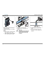
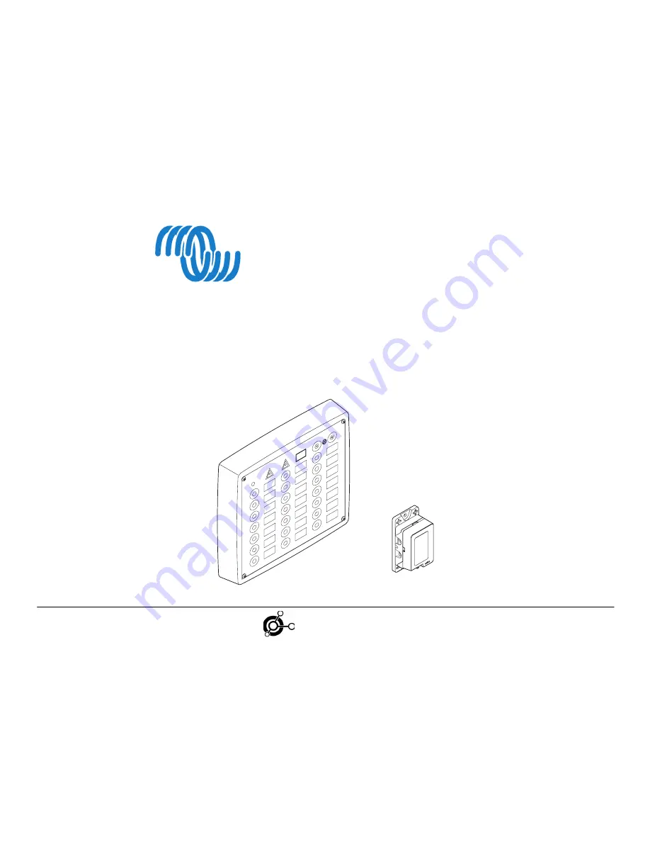
background image


       VE.NET DC 


Bus-based power distribution system 

Installation & Operation manual 

victron energy

B   L   U   E        P   O   W   E   R

Summary of Contents for VE.Net DC

Page 1: ...VE NET DC Bus based power distribution system Installation Operation manual victron energy B L U E P O W E R ...

Page 2: ...E REGARDING THESE VICTRON ENERGY PRODUCTS AND MAKES SUCH VICTRON ENERGY PRODUCTS AVAILABLE SOLELY ON AN AS IS BASIS IN NO EVENT SHALL VICTRON ENERGY B V BE LIABLE TO ANYONE FOR SPECIAL COLLATERAL INCIDENTAL OR CONSEQUENTIAL DAMAGES IN CONNECTION WITH OR ARISING OUT OF PURCHASE OR USE OF THESE VICTRON ENERGY PRODUCTS THE SOLE AND EXCLUSIVE LIABILITY TO VICTRON ENERGY B V REGARDLESS OF THE FORM OF A...

Page 3: ...m 19 Priority 19 Switch mode 19 Navigation lights 19 Bilge pump 19 Feedback defective lamp cable 19 Reconfigure 19 Store the configuration 19 2 3 Start the system the first time 20 Configure one switch to one node 21 Configure one switch to more than one node 21 Configure more than one switch to one node 22 Change priority 22 Change feedback of defective lamp wire 23 Delete connection between swit...

Page 4: ...A warning for broken navigation light or wire A warning for overloads The appliance turns off automatically A warning for low voltage The appliance turns off automatically An adjustable background light in the switch panel About this manual This user manual describes the installation and operation of the VE Net DC system Read this manual carefully before use or operation of the product In case you...

Page 5: ... A direct power node 20 A direct power node 2 15 m bus cable 8 m cable for push button panel 8 m cable for bilge pump 8 m cable for instruments B Push button panel C 3 A power nodes D 10 A power nodes E 16 A power nodes F Sensor node for bilge pump G Cable cutter H DC 4 compound tube I CD labels B 1x A 1x C 5x 16 10 3 G 1x I 1x H 1x D 8x E 2x F 1x S ...

Page 6: ... a short circuit of exposed terminal connectors Always use the correct tool Always take the necessary precautions to protect the components and cables from damage Always clamp the wires at least every 30 cm 12 Protect cables that pass bulkheads or structural members against damage by grummets or equivalent means Protect components and wires with sheets conduits or equivalent means when there is a ...

Page 7: ... 2 Divide the appliances as evenly as possible between the two bus cables Each bus cable can have a maximum load of 50 A 3 Select the node with the correct amperage Refer to Select the nodes 4 Write down the configuration of the nodes in the Configuration tables Refer to the Error Not a valid bookmark self reference Warning Do not install nodes in a petrol engine compartment or a gas locker There ...

Page 8: ...uments Interior light Power outlet Refrigerator 16 A Fresh water pump 2 5 14 Bilge pump Sensor node on off Automatic switch bilge pump 1 5 16 Note Connect the delivered sensor node to the automatic switch of the bilge pump Caution The node triggers when there is more power applied than specified Caution Connect the radar compass GPS and bilge pump to a direct power node The direct power nodes are ...

Page 9: ...t the wires from the appliance to where the node will be placed 2 Cut the wires to the correct length Allow extra length to tighten up the cables with tie wraps Refer to the drawing 3 Attach the connectors on the end of the wires 4 Lay out single appliances directly to the node 5 Lay out group appliances parallel to the node ...

Page 10: ...hey will be placed Note Make sure the main fuse box is easy to access Warning Do not install nodes in a petrol engine compartment or a gas locker There is a risk of ignition and explosion Note Make sure that the cable between the fuse box and the battery has a maximum length of 200 cm 80 Warning If the cable red between the main fuse box and the battery is longer than 200 cm 80 it needs a fuse of ...

Page 11: ...the main fuse box 1 Remove the cover of the main fuse box Note Make sure the main fuse box is easy to access 2 Install the main fuse box on a suitable surface 3 Set the fuses in the OFF position 4 Replace the front cover Warning Make sure all fuses are set in the OFF position ...

Page 12: ...e insulation 6 Place the wire back on its place 7 Tighten the screw to secure the wire 8 Clamp the bundles of red and black battery wires with at least 20 mm 6 8 distance in between 9 Connect the red cable to the terminal on the battery 10 Connect the black cable to the terminal on the battery Note Do the procedure for one wire at a time Warning Follow the instructions properly to reduce the risk ...

Page 13: ...ferent instruments and the node Refer to the illustration 3 Clamp the 20 A DPN wires to the bilge pump Note Do not connect the wires to the appliances mentioned 4 Attach the wires for the push button panel Leave 30 40 cm 12 16 extra length for easy connection of the switch panel 5 Attach the wires with a clamp every 30 cm 12 Note Clamp the wires of the instruments bilge pump and switch board separ...

Page 14: ...ve the cover of the switch panel Note Handle the cover with the electronics with care Do not touch the electronics Place the cover with the electronics in the box during installation 2 Feed the wires through a 20 mm 6 8 hole 3 Feed the wires through the back panel 3 Install the back panel on a suitable surface ...

Page 15: ...olet Black Red Bus GND VBAT 4 Insert the labels in the cover Note Switch 1 and 4 are reserved for the bilge pump If necessary make new labels with the delivered CD Use an overhead sheet to print the labels 5 Connect the wires to the electronics 6 Replace the front cover ...

Page 16: ...side of the node marked with with the red bus cable Align the side of the node marked with with the black bus cable 2 Push the wires into the base 3 Mark the places of the clips on the wires Warning Do not use the node base and the clips more than one time Mounting deforms the clips and base 4 Cut the insulation with the cable cutter 5 Bend the wire several times until 2 mm 1 10 of the conductors ...

Page 17: ...ntact with the exposed wires 7 Put some DC4 compound around the clips 8 Push the clips into place to secure 9 Repeat these steps for the other wire 10 Put some DC4 compound around the violet wire Put the compound on the place of the single clip 11 Push the wire into its position 12 Use a hammer to secure the clip in the base ...

Page 18: ...rs to the wires and clamp them accordingly Caution Do not connect the wires to the node This will be done during the configuration of the system 16 Attach the wires with a clamp every 30 cm 12 Allow some space for additional nodes to install 17 On the end of the bus cable Cut the bus cables to the proper length and insulate them with insulating tape ...

Page 19: ... Configure each lamp to a separate switch and a separate node The indication shows which light is defective 3 Configure each lamp to a separate node but to the same switch Combined with a VE Net DC Navigation light board it is easy to see which light is defective Bilge pump The bilge pump and its sensor node do not need to be configured They are set in the factory on switch 1 automatic and switch ...

Page 20: ...in fuses 2 Switch on the push button panel Warning In case of immediate alarm buzzer and lightening of the polarity warning led 1 Turn of the system through the main fuses immediately 2 Check the polarity at the batteries Change if necessary 3 Turn on the system again See chapter Maintenance 3 Proceed with configuration ...

Page 21: ...appliance to the node The display shows C2 The buzzer gives a signal 3 Push the desired push button Push shortly to select toggle mode The display turns off and the buzzer stops Push for 5 seconds to select direct mode The display shows C3 and the buzzer stops Configure one switch to more than one node Use the above procedure Repeat the procedure for each node that you want to connect to the switc...

Page 22: ...ly 4 Push the desired switch shortly The switch is configured automatically to the same mode as the first switch The display turns off Change priority C1 2 sec P0 P1 x 2 1 Push the and for two seconds The display shows C1 2 Push the 2 times shortly The display shows P0 3 Push the to set the priority The display shows P1 P2 or P3 P1 is high priority 4 Push the switch button that corresponds to the ...

Page 23: ...he display shows Fb Feedback 3 Push the to set the feedback F1 Feedback on F0 Feedback off recommended for refrigerator automatic running motor and groups of separately switched appliances 4 Push the switch button that corresponds with the node The display turns off Note Be aware that an automatic motor and appliances with separate conventional switches when not activated will indicate defective l...

Page 24: ...o seconds The display shows C1 2 Push the 4 times shortly The display shows rS Reset 3 Push switch to delete shortly The switch illuminates green and the appliance switches on 4 Turn off and on the push button panel to store the deleted function The green light and the appliance turn off The connection between the switch and the node is deleted ...

Page 25: ...ton panel overview A On off B Push button C Label D Warning light Over current E Warning light Polarity F Display G Button background light configuration H Button background light configuration over current polarity B C A D E F G H 1 4 10 7 13 16 19 2 5 11 8 14 17 20 3 6 12 9 15 18 21 C3 ...

Page 26: ...ode to turn on the corresponding appliance A green light in the switch button indicates that the corresponding node is turned on Background light When the switch panel is turned on the background light is illuminated in the medium level level 4 1 Push to increase the level of the background light The maximum level is 6 A beep signals that this level is reached 2 Push to decrease the level of the b...

Page 27: ...tically in order of priority Indications of the appliances Each appliance is automatically tested during its operation In that case the light in the switch button is green Other indications in the push buttons are explained in the table In case of a failure turn off the appliance with the push button The buzzer indication led and automatic fuse are reset Repair the appliance Switch on the applianc...

Page 28: ... U E P O W E R Detection of doors and hatches The buttons on the switch panel can be used for detection if a door or a hatch is opened For this purpose a special sensor node is necessary Light Meaning Door hatch switch closed Red Door hatch switch open ...

Page 29: ... Digital power on Direct power on power off Appliances that are connected to a direct power node are normally switched on by the switch board In case of malfunction of the switch board 1 Push the bypass fuse on the direct power node to switch on the appliance In case the appliance cannot be turned off with the switch board 2 Release the power fuse of the direct power node ...

Page 30: ...p operates while you turn off the system it stays in operation Warning Always Turn off all fuses in the main fuse box before you start working on the electrical system Note In case it is preferred to leave some appliances e g refrigerator alarm installation in operation it is necessary to leave the system on To minimize the power consumption of the system decrease the background light Refer to Bac...

Page 31: ...heck the red plus wire Reset the fuse Check the connections between bus cable an the node Reconnect if necessary Overload light is illuminated a interrupted beep is heard The voltage is low The circuit is overloaded Turn off appliances If not the system turns off appliances automatically by order of priority Switch blinks red a beep is heard Short circuit between node and appliance Check the wires...

Page 32: ... type 6 Configure the node Refer to Configure the system If no new nodes are available Warning Use this procedure only in case of an emergency and when no spare parts are available Warning Make sure the and cables cannot make contact with each other Possible risk of short circuit For appliances connected via a power node 1 Disconnect the node Follow steps 1 to 4 of the procedure on the left 2 Plac...

Page 33: ... F to 158 F Operational temperature 4 ºC to 50 ºC 24 F to 122 F Maximum bus cable length 100 m 328 ft Maximum number of nodes 255 Maximum length of bus cables for boats 15 m 50 ft Maximum load with 15 m of bus cable 50 A Maximum number of bus cables Indefinite Weight of a 130 A system with 20 nodes 20 kg 44 lbs Complies to 94 25 EC and 89 336 EEC International standards ISO 10133 CE approval Yes E...

Page 34: ...Installation operation manual 34 victron energy B L U E P O W E R 4 4 Spare parts 1 2 11 10 9 8 3 5 4 6 12 13 14 15 16 17 18 19 20 15m 7 ...

Page 35: ...6 Fuse 20 A DPNF20A 0 7 Cabling bus 50 A complete CB50A 0 8 Cable cutter CC16 0 9 Dielectric gel DC4 0 10 Frame 21 keys Navigation light FPB21NL 0 11 Push button plate PBP21K12V 0 12 Node base single NB1 0 13 Power node 16 A PN16A 0 14 Power node 10 A PN10A 0 15 Power node 3 A PN3A 0 16 Branch node BN 0 17 Sensor node switch 12 V SNS12V 0 18 Sensor node open close 12 V SNOC12V 0 19 Sensor node lev...

Page 36: ...Installation operation manual 36 victron energy B L U E P O W E R 5 Appendix The following sections can be used and when necessary removed from this manual Configuration table 3x ...

Page 37: ...Installation operation manual 37 victron energy B L U E P O W E R Configuration table Bus cable number Type node Serial nr Priority Switch nr Type of appliance Amperage Total amperage for the bus cable ...

Page 38: ...Installation operation manual 38 victron energy B L U E P O W E R Configuration table Bus cable number Type node Serial nr Priority Switch nr Type of appliance Amperage Total amperage for the bus cable ...

Page 39: ...Installation operation manual 39 victron energy B L U E P O W E R Configuration table Bus cable number Type node Serial nr Priority Switch nr Type of appliance Amperage Total amperage for the bus cable ...

Page 40: ...Victron Energy B V De Paal 35 1351 JG ALMERE The Netherlands www victronenergy com info victronenergy com victron energy B L U E P O W E R ...

Reviews: