background image

MST719  Service  Manual         


[

SERVICE MANUAL

]


Mstar MST719DU   

Summary of Contents for Mstar MST719, Mstar MST719DU

Page 1: ...MST719 Service Manual 1 SERVICE MANUAL Mstar MST719DU ...

Page 2: ... Pins function description 15 4 TDA9885TS IC Introduction 17 1 Features description 17 2 Pins function description 21 5 PCM1808 ADC IC Introduction 22 6 SN74LVC1GX04DCK IC Introduction 23 7 EN25F40 IC Introduction 24 8 CS4344 IC Introduction 25 9 Other ICs introduction 26 10 Connectors and electronics parameter 27 11 Usual fault 30 1 Can t work 30 2 Back lamp can t be on 31 3 Image abnormity 32 4 ...

Page 3: ...MST719 Service Manual 3 1 warning High voltage don t touch it when it s working 2 Please confirm the power to Panel is 5V when change main board if not the panel can t work or be damage ...

Page 4: ...04 HDCP DVD socket PI5V330 DVD socket U19 CVBS YPbPr YPbPr CVBS_Out CVBS CVBS Y C Audio R L Audio R L Audio Out AMP HDMI DAC CS4344 DVD R L Audio out Audio R L Out TV Audio IF NXP LCD Panel Connect LIPS Power IR LED KEY Board IR Board Speaker 2D interlace 2D Combfilter MSTAR IC U26 U14 U10 U20 U21 U16 U27 U18 U4 U7 U8 U9 U6 U13 24C32 FLASH EN25F40 EEPROM CN21 RC4558 AV2 AV_OUT Tuner S Video YPbPr ...

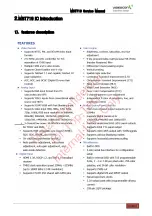
Page 5: ...MST719 Service Manual 5 2 MST719 IC Introduction 1 features description ...

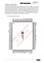
Page 6: ...MST719 Service Manual 6 ...

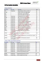
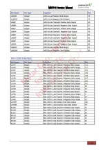
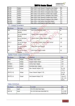
Page 7: ...MST719 Service Manual 7 2 Pins function description ...

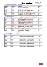
Page 8: ...MST719 Service Manual 8 ...

Page 9: ...MST719 Service Manual 9 ...

Page 10: ...MST719 Service Manual 10 ...

Page 11: ...MST719 Service Manual 11 ...

Page 12: ...MST719 Service Manual 12 ...

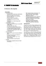
Page 13: ...MST719 Service Manual 13 3 TAS5707 IC Introduction 1 Features description ...

Page 14: ...MST719 Service Manual 14 ...

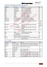
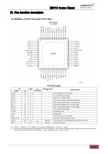
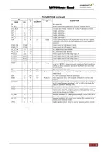
Page 15: ...MST719 Service Manual 15 2 Pins function description ...

Page 16: ...MST719 Service Manual 16 ...

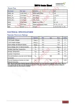
Page 17: ...MST719 Service Manual 17 4 TDA9885 IC Introduction 1 features description ...

Page 18: ...MST719 Service Manual 18 Block diagram ...

Page 19: ...MST719 Service Manual 19 ...

Page 20: ...MST719 Service Manual 20 ...

Page 21: ... TOP for resistor adjustment 10 SDA I2C bus data input and output 11 SCL I2C bus clock input 12 SIOMAD Sound intercarrier output and MAD select with resistor 13 n c Not connected 14 TAGC Tuner AGC output 15 REF 4 MHz crystal or reference signal input 16 VAGC VIF AGC for capactior 17 CVBS Composite video output 18 AGND Analog ground 19 VPLL VIF PLL for loop filter 20 Vp Supply voltage 21 AFC AFC ou...

Page 22: ...MST719 Service Manual 22 5 PCM1808 ADC IC Introduction For all sound source ADC ...

Page 23: ...MST719 Service Manual 23 6 SN74LVC1GX04DCK IC Introduction ...

Page 24: ...MST719 Service Manual 24 7 EN25F40 IC Introduction ...

Page 25: ...MST719 Service Manual 25 8 CS4344 IC Introduction HDMI Sound DAC ...

Page 26: ...l module DVD or USB with YPbPr signal switch If not use DVD or USB function this IC no need install c RC4558 U4 for AV output audio amplifier because the external audio signal by 74hc4502D switched the audio level not enough under 620MVrms d 24C04 U7 U8 for VGA and HDMI DDC memory e 24C32 U21 for EEPROM f 24C04 U19 for HDMI EDID HDCP ...

Page 27: ...MST719 Service Manual 27 10 Connectors and electronics parameter 1 System connection block diagram as follow Note S Video YPbPr Audio input Common AV1 Audio sockets input ...

Page 28: ...LK_EN Back lamp ON OFF ON 4 3V OFF 0 0 8V CN11 AUDIO OUTPUT CONN NO Symbol Function Electronic parameter 1 L_OUT L_OUT positive 2 L_OUT L_OUT negative 3 R_OUT R_OUT negative 4 R_OUT R_OUT positive CN18 Key CONN NO Symbol Function Electronic parameter 1 KEY0 ADC Volt input 0 03 1 6V 2 KEY1 ADC Volt input 0 03 1 6V 3 GND 0V CN19 LED IR CONN NO Symbol Function Electronic parameter 1 RMT IR input Vpp ...

Page 29: ... 3V Option 3 3V CN14 Panel LVDS CONN NO Symbol Function Electronic parameter 1 VCC 5V 2 VCC 5V 3 GND 4 VCC 5V 5 GND 6 GND 7 RXO0 Vpp 3 3V 8 RXO0 Vpp 3 3V 9 RXO1 Vpp 3 3V 10 RXO1 Vpp 3 3V 11 RXO2 Vpp 3 3V 12 RXO2 Vpp 3 3V 13 GND 14 GND 15 RXOC Vpp 3 3V 16 RXOC Vpp 3 3V 17 RXO3 Vpp 3 3V 18 RXO3 Vpp 3 3V 19 RXE0 Vpp 3 3V 20 RXE0 Vpp 3 3V 21 RXE1 Vpp 3 3V 22 RXE1 Vpp 3 3V 23 RXE2 Vpp 3 3V 24 RXE2 Vpp ...

Page 30: ...chassis problem if still abnormity the power supply board problem N Y Check if the I2C of U18 pin61 pin62 and the U21 I2C pin software data is ok Check U20 flash IC is work and the software data normal operation Check if the crystal is work it frequency is 12M check the Q28 reset circuit normal working N N Y Y N LED Not on can t power on If all the work condition are ready but still can t power on...

Page 31: ...heck the power supply inverter part Check the component Q7 and the relevant circuit work normal Then check MST719 pin55 control level is low N Y Y Check if the voltage of the CN21 pin4 STB on off is high level to 4 5V N Check the pin voltage of the connector CN21 pin 11 Bright on off control is high level to 4 0V Y Y ...

Page 32: ...ut is ok As per input source picture abnormity Check TV source of TDA9885 tuner ect circuit AV S Video VGA Ypbpr HDMI socket to MST719 input circuit 1 Change the LVDS line 2 If have not 5V power supply Check U3 5V switch and MST719 I O control circuit 1 Check the component of CN14 2 Check the MST719 IC work circuit If all the work condition are ready but still picture abnormity try to change MST71...

Page 33: ...t sound output to speaker need check this IC work status please check the power supply 3 3V and 5VS is ok or not 2 U28 is the crystal oscillation driver IC check the pin6 3 3V is OK then check the frequency of pin6 is 12 288M Check the power supply circuit or change the component of crystal Check the audio switch ICs U14 U26 power supply voltage is ok check the logic control is ok Y Y Check the po...

Reviews: