background image


ViewSonic VG930m-3 

VA930m-1 

Model No. VS11369 

19” Color TFT LCD 

Display 


(VG930m-3_VA930m-1_SM Rev. 1a Oct. 2006) 

ViewSonic 381 Brea Canyon Road, Walnut, California 91789 USA - (800) 888-8583


Service Manual 

Summary of Contents for VG930M - 19" LCD Monitor

Page 1: ...ViewSonic VG930m 3 VA930m 1 Model No VS11369 19 Color TFT LCD Display VG930m 3_VA930m 1_SM Rev 1a Oct 2006 ViewSonic 381 Brea Canyon Road Walnut California 91789 USA 800 888 8583 Service Manual ...

Page 2: ...her expressed or implied with respect to the contents hereof and specifically disclaims any warranty of merchantability or fitness for any particular purpose Further ViewSonic reserves the right to revise this publication and to make changes from time to time in the contents hereof without obligation of ViewSonic to notify any person of such revision or changes Trademarks Optiquest is a registered...

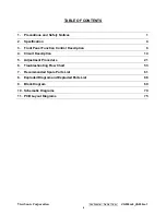
Page 3: ...ety Notices 1 2 Specification 4 3 Front Panel Function Control Description 8 4 Circuit Description 14 5 Adjustment Procedure 21 6 Troubleshooting Flow Chart 53 7 Recommended Spare Parts List 61 8 Exploded Diagram and Exploded Parts List 66 9 Block Diagram 69 10 Schematic Diagrams 70 11 PCB Layout Diagrams 75 ...

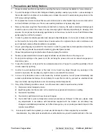
Page 4: ...nd instructions that accompany the monitor 8 Please pay special attention to power supply overloads as electrical shock or fire may occur 9 Do not place anything on the power cord Do not hang the power cord over an area where people or objects may pass 10 In case the monitor is not be used for an extended period turn off power to avoid the possibility of short circuits caused by lightning 11 In or...

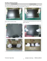
Page 5: ...ds Incorrect methods Only touch the metal frame of the LCD panel or the front cover of the monitor DO not touch the surface of the POL Surface of the LCD panel is pressed by fingers and that may cause mura Take out the monitor with cushions Taking out the monitor by grasping the LCD panel that May cause mura ...

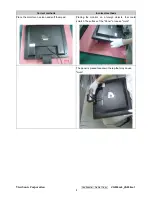
Page 6: ...0m 3_VA930m 1 3 Correct methods Incorrect methods Place the monitor on a clean and soft foam pad Placing the monitor on a foreign objects that could scratch The surface of the Panel or cause mura The panel is placed facedown the lap that may cause mura ...

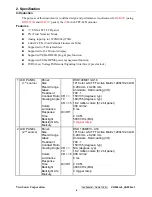
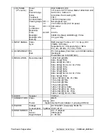
Page 7: ...t source Panel Size Pixel Arrange Glass Treatment Contrast Ratio Viewing Angle Colors Luminance Response Time Backlight Backlight Life Mercury CR 10 CR 5 On Off HSD190ME13 A16 19 Color a Si TFT Active Matrix 1280x1024 LCD 0 294 mm x 0 294 mm Anti Glare Hard coating 3H 700 1 150 135 degrees typ 160 155 degrees typ 16 2 million colors 6 2 bit panel 300 cd m2 8 ms 4 CCFL 50000 Hrs Min 3 mg per lamp 2...

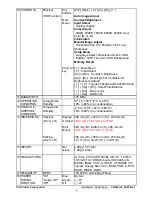
Page 8: ...eparate Sync Composite Sync SOG Fh 24 82 kHz Fv 50 75 Hz 4 COMPATIBILITY PC Mac PC Compatibles from VGA up to 1280x1024 Non Interlaced Power Mac up to 1280X1024 5 RESOLUTION Recommended 1280x1024 60Hz 640 x 350 70Hz 640 x 400 60 70Hz 640 x 480 50 60 67 72 75Hz 720 x 400 70Hz 720 x 480 60Hz 720 x 576 50Hz 800 x 600 50 56 60 72 75Hz 832 x 624 75Hz 1024 x 768 50 60 70 75Hz 1152 x 864 75Hz 1152 x 870 ...

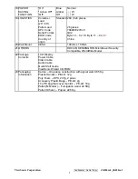
Page 9: ...e 1 Dn Power Lock 1 Up OSD Lock 11 BANDWIDTH 135 MHz 12 OPERATING CONDITION Temperature Humidity 32 F to 104 F 0 C to 40 C 10 to 90 no condensation 13 STORAGE SHIPPING CONDITION Temperature Humidity 4 F to 140 F 20 C to 60 C 10 to 90 no condensation 14 DIMENSIONS Physical W x H x D Packing W x H x D Display w Stand Wall Mount 428 mm W x 479 mm H x 230 mm D 16 8 W x 18 8 H x 9 0 D 428 mm W x399 mm ...

Page 10: ...yte 11 0 x 99 China 20 Wall Mount VESA 100mm x 100mm 21 OTHERS DDC 2B KENSINGTON MicroSaver Security Compatible WorldWide Model 22 Package Contents LCD Display Power Cable Video Cable Audio Cable Quick Start Guide ViewSonic Wizard CD ROM 23 Packaging Information Carton One piece construction with signal wall 0 65 Kg Plastic Handle PE LD 12g Poly Foam EPS 207g 2 pices Accessory Plastic Bags PE LD 2...

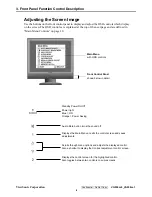
Page 11: ...efined in Main Menu Controls on page 10 Main Menu with OSD controls Front Control Panel shown below in detail Scrolls through menu options and adjusts the displayed control Also a shortcut to display the Contrast adjustment control screen Power light Blue ON Orange Power Saving Standby Power On Off Displays the Main Menu or exits the control screen and saves adjustments Audio Mute button turns the...

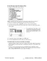
Page 12: ...p S or down T buttons 5 To save the adjustments and exit the menu press button 1 twice The following tips may help you optimize your display Adjust the computer s graphics card so that it outputs a 1280 x 1024 60Hz video signal to the LCD display Look for instructions on changing the refresh rate in the graphics card s user guide If necessary make small adjustments using H POSITION and V POSITION ...

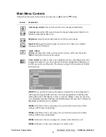
Page 13: ...nt modes including preset color temperatures and a User Color mode which allows independent adjustment of red R green G and blue B The factory setting for this product is 6500K 6500 Kelvin sRGB This is quickly becoming the industry standard for color management with support being included in many of the latest applications Enabling this setting allows the LCD display to more accurately display col...

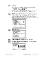
Page 14: ...nformation displays the timing mode video signal input coming from the graphics card in the computer the LCD model number the serial number and the ViewSonic website URL See your graphics card s user guide for instructions on changing the resolution and refresh rate vertical frequency NOTE VESA 1280 x 1024 60Hz recommended means that the resolution is 1280 x 1024 and the refresh rate is 60 Hertz M...

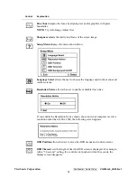
Page 15: ...ws the user to choose the language used in the menus and control screens Resolution Notice allows the user to enable or disable this notice If you enable the Resolution Notice shown above and your computer is set at a resolution other than 1280 x 1024 the following screen appears OSD Position allows the user to move the OSD menus and control screens OSD Timeout sets the length of time the OSD scre...

Page 16: ...0m 1 13 Control Explanation OSD Background allows the user to turn the OSD background On or Off Memory Recall returns the adjustments back to factory settings if the display is operating in a factory Preset Timing Mode listed in the Specifications of this manual ...

Page 17: ...6Pin NO Symbol Description 9 NC DC Output 24 0 10 Vdc 50mA Optional 8 NC DC Output 12 10 Vdc 200mA Optional 7 6 BL Adj Luminance Control 0Vdc 3 3Vdc CON802 6 5 ON OFF ON 3 3Vdc or 5 0Vdc OFF 0V 4 5 3 4 DC Output 5 0 5 Vdc 2500mA 2 3 1 2 GND GND 1 NC DC Output 8 10 Vdc 100mA Optional 1 1 H V High Voltage CON901 CON904 2 2 Return Return Pin ...

Page 18: ...and output line short between and 3 Criterion for Judging PASS 1 3 SHORT TEST PROTECT 24Vdc SHORT to GND POWER PROTECT 12Vdc SHORT to GND POWER PROTECT 5Vdc SHORT to GND POWER PROTECT 8Vdc SHORT to GND POWER PROTECT 1 4 LOW POWER CONSUMPTION Input 240Vac 50Hz Output NO LOAD Power Consumption 0 5W 1 5 GROUND TEST 1 Test Requirements Input Current 25A Measurement Time 3sec Temperature 25 5 2 A metho...

Page 19: ...DOWN 2 2 KICK OFF VOLTAGE TEST Test Condition ON OFF PIN 3 3Vdc or 5 0Vdc BL Adj PIN 3 3Vdc or 5 0Vdc Result CN901 CN903 TEST CN904 H V PIN Output Voltage 1 5KV rms CN902 CN904 CONNECT TEST CN901 H V PIN Output Voltage 1 5KV rms CN903 CN904 CN901 CONNECT TEST CN902 H V PIN Output Voltage 1 5KV rms CN901 CN902 CN904 CONNECT TEST CN903 H V PIN Output Voltage 1 5KV rms 2 3 OUTPUT CURRENT TEST Test Co...

Page 20: ...NT TEMPERATURE 0 40 2 WORK ENVIROMENT humidity 30 85 RH 3 STORE ENVIROMENT TEMPERATURE 25 85 4 STORE ENVIROMENT humidity 30 90 RH INPUT REQUIREMENT AC Input Voltage 100Vac 240Vac 50 60Hz SPEC NO List CH 1 CH 2 CH 3 CH4 1 Channel Name 8V Optional 5V 12V Optional 24V 2 OUTPUT VOLTAGE SPEC 8V 10 5V 5 12V 11 5 13 5V 24V 10 1 900mA for 3 OUPUT CURRENT SPEC 50mA 2500mA 200mA Inverter 2 50mA for SIP PANE...

Page 21: ... 12V ADJ On Off 5V GND 8V PIN NO FOR LVDS NC NC 6 5 4 3 2 1 NC PANEL SPEC NC NC ADJ On Off 5V GND NC OUTPUT VOLTAGE RISE TIME AC INPUT 90 Vac 264Vac 100mS AC ELECTRICITY TIME DELAY WHEN AC INPUT OUTPUT VOLTAGE SHOULD WITHIN 1 5S SURGE ELECTRI CURRENT AC INPUT 240Vac PROTECT FOR SHORT CIRCUIT PROTECT FOR OVER CURRENT ...

Page 22: ...DUCTION 17 and 19 PANEL LCD MONITOR 1 1 4 lamp type of 17 and 19 PANEL 2 2 SPEC REQUIREMENT Items Sign Condition Min Typ Max BL ADJ 0V 3 0 3 5 4 0 6 0 6 5 7 5 1 Output Current mA Lout1 2 Vin 24V BL ADJ 3 3V 6 5 7 0 7 5 7 0 7 5 8 0 2 Output Voltage Vrms Vin 24V BL ADJ 3 3V 560 660 760 3 Lamp Frequency kHz f Vin 24V BL ADJ 3 3V 45 50 55 On Vin 24V On Off 3 3V or 5V Normal Operation 4 On Off Control ...

Page 23: ...4 4A 9D 24 14 4F 54 BF EF 80 81 80 81 40 71 4F 01 01 01 01 01 01 01 01 01 01 30 2A 00 98 51 00 2A 40 30 70 13 00 78 2D 11 00 00 1E 00 00 00 FF 00 51 43 32 30 36 30 31 30 30 30 30 31 0A 00 00 00 FD 00 32 4B 1E 52 0E 00 0A 20 20 20 20 20 20 00 00 00 FC 00 56 47 39 33 30 6D 2D 33 0A 20 20 20 20 00 E9 4 5 Interface 4 5 1Pin Assignment D SUB connector CN2 Pin Input Signal Pin Input Signal Pin Input Sig...

Page 24: ...ViewSonic Corporation Confidential Do Not Copy VG930m 3_VA930m 1 21 5 Adjusting Procedure Setup Procedure ...

Page 25: ...ViewSonic Corporation Confidential Do Not Copy VG930m 3_VA930m 1 22 ...

Page 26: ...ViewSonic Corporation Confidential Do Not Copy VG930m 3_VA930m 1 23 Installation will create a icon for ISP application in START MENU PROGRAM Press finish button exit setup ...

Page 27: ...able 25pin 1 AC power cable 1 ISP fire cord the fixture is made in TE for firmware upgrade 1 Power adapter for firmware upgrade this adapter is made in TE 1 A computer with WindowsXP VG930 monitor no firmware a additional monitor for system display ISP ISP3 0 program 2 VG930 monitor upgrade firmware by ISP Cord NOTE The fixture for firmware upgrade provide two different method to fire Please check...

Page 28: ...ViewSonic Corporation Confidential Do Not Copy VG930m 3_VA930m 1 25 LPT Cable AC power Cable VGA Cable USB FOR PRINT ISP3 0 SOFT TEST PC Fixture ISP_CORD Fixture POWER_ADAPTER LPT PORT ...

Page 29: ... 17 2 4 Firmware Upgrade Procedure Step17 2 4 1 connect all kinds of cable with PC ok turn on the computer and open the ISP EXE Step17 2 4 2 The ISP EXE application is running as the below picture Press the create security file Button to create a security file Isp exe ...

Page 30: ...t first key in or press the up toward key to change the command number to 4 second key 94 94 AC CA 53 in the ISP slave add Slave b add Command1 Command2 command3 table the below form showed the data list Setp17 2 4 4 Select MTV Type in the MTV type list VG930 monitor must be choose the MTV512M64 option ...

Page 31: ...e to fire Click the load MCU file button to entry to interface of setting current path and select the BIOS file in the disk Step17 2 4 6 Select the program upgrade made must be select autorun mode at this 2 Entry to interface of selecting file 3 Open file and load file ok 4 Check the BIOS checksum ...

Page 32: ...poration Confidential Do Not Copy VG930m 3_VA930m 1 29 Step17 2 4 7 click the run button to upgrade monitor s firmware Step17 2 4 8 Firmware is upgraded ok please check the data of S W CRC H W CRC CHECKSUM MAX ADDR ...

Page 33: ...DC Key In again 17 3 1 Equipment Needed VG730 Series Monitor RS232 VGA Cable 1 RS232 DVI Cable 1 AC POWER Cable 1 TEST PC with WindowsXP Display Data Channel D8330 DDC Card to plug PC_PCI _Slot DYNACOLOR DDC Tester System software Barcode Scanner 1 AC POWER Source one additional monitor for Test System displaying RS232 VGA Cable AC POWER Cable RS232 DVI Cable DDC TESTER SOFT PC DDC CORD Barcode Sc...

Page 34: ...onnect RS232 DVI cable to DDC RS232 OUT port of PC if you do DDC key In for D_DVI NOTE Barcode Scanner and Keyboard pluged in Keyboard port of computer together 17 3 2 3 DDC TESTER SYSTEM SOFT SETUP from setup file NOTE Before install DDC Tester System Soft please checking the D8330 CORD is plugged Or the DDC Tester application could t be run 17 3 2 3 1 Install DDC Tester System by selecting and c...

Page 35: ...ViewSonic Corporation Confidential Do Not Copy VG930m 3_VA930m 1 32 ...

Page 36: ...ViewSonic Corporation Confidential Do Not Copy VG930m 3_VA930m 1 33 ...

Page 37: ...ViewSonic Corporation Confidential Do Not Copy VG930m 3_VA930m 1 34 DDC Key In Procedure Step 1 select and execute DDC Key In program winDDC exe icon on desktop ...

Page 38: ...tion Confidential Do Not Copy VG930m 3_VA930m 1 35 Step 2 Load DDC source file Step2 1 Choose File menu click Model Edit and entry model edit ialog box Step2 2 Press Brower button set current DDC_LOAD_FILE working path ...

Page 39: ...nic Corporation Confidential Do Not Copy VG930m 3_VA930m 1 36 Step2 3 click working Model select Model in list box Step2 4 Return to main windows of WinDDC exe And choose DDC file in work Model down list box ...

Page 40: ...e input barcode icon at the toolbar Key in the serial number or Use Barcode Scanner to scan the barcode of the monitor and press the enter key Step 4 The successful picture is as follows The EDID data Description will appear the bottom of windows The EDID Data will appear the top of windows ...

Page 41: ...930m 1 38 Step 5 Checking Methods Step5 2 open up the my computer attribute dialog box select the hardware option open up drive management Below the monitor catalog uninstall the monitor Step5 3 Scan the hardware change until system find the new monitor driver ...

Page 42: ...ViewSonic Corporation Confidential Do Not Copy VG930m 3_VA930m 1 39 Step5 4 Select and click the EDIDW2K EXE file the EDID information will show on the screen Setp5 5 Ckeck the DDC ...

Page 43: ...ViewSonic Corporation Confidential Do Not Copy VG930m 3_VA930m 1 40 Packing For Shipping And Disassembly Procedure ...

Page 44: ...ViewSonic Corporation Confidential Do Not Copy VG930m 3_VA930m 1 41 Disassembly Procedure 1 Take down the cover of bracket 2 4PCS Take down fixed screws on hinge ...

Page 45: ...ViewSonic Corporation Confidential Do Not Copy VG930m 3_VA930m 1 42 3 3PCS Take down the rear cover screws 4 Take apart the rear cover ...

Page 46: ...n Confidential Do Not Copy VG930m 3_VA930m 1 43 5 Take down the speaker for right left 6 Take down fixed wire of speaker Unplug the wire of speaker 7 Take down fixed ALT of wire on key board then Unplug wire of main board ...

Page 47: ...ViewSonic Corporation Confidential Do Not Copy VG930m 3_VA930m 1 44 8 Take down the screws on key board 9 Take down the ALT of wire on lamp ...

Page 48: ...nic Corporation Confidential Do Not Copy VG930m 3_VA930m 1 45 10 Take down the screws on screen cover 11 Take down the ALT of wire with main board power board 12 Take down fixed the FFC ALT Take down the FFC ...

Page 49: ...ViewSonic Corporation Confidential Do Not Copy VG930m 3_VA930m 1 46 13 Take down the FFC ...

Page 50: ...ViewSonic Corporation Confidential Do Not Copy VG930m 3_VA930m 1 47 14 Unplug the linked wire with main board lamp 15 Take down the screws of power board then take down the power board ...

Page 51: ...ViewSonic Corporation Confidential Do Not Copy VG930m 3_VA930m 1 48 ...

Page 52: ...ViewSonic Corporation Confidential Do Not Copy VG930m 3_VA930m 1 49 16 Take down the screws of main board then take down the main board ...

Page 53: ...ViewSonic Corporation Confidential Do Not Copy VG930m 3_VA930m 1 50 17 Tear down the around hook outside and then take down the Bezel ...

Page 54: ...ViewSonic Corporation Confidential Do Not Copy VG930m 3_VA930m 1 51 18 Take down the main hob around the sides of screws and then take down the main hob ...

Page 55: ...ViewSonic Corporation Confidential Do Not Copy VG930m 3_VA930m 1 52 ...

Page 56: ...ration Confidential Do Not Copy VG930m 3_VA930m 1 53 6 Troubleshooting Flow Chart Main Procedure Start Connect all of devices to the LCD monitor Power On Is indicator LED light A Power Circuit Troubleshooting Yes No 1 ...

Page 57: ...m 3_VA930m 1 54 Is backlight on Display Performance O K Function Adjustment O K Audio Function O K No Trouble Found End B Backlight Troubleshooting C Performance Troubleshooting D Function Troubleshooting E Audio Troubleshooting Yes Yes Yes No No No No 1 ...

Page 58: ...ViewSonic Corporation Confidential Do Not Copy VG930m 3_VA930m 1 55 A Power Circuit Troubleshooting Start Change AC DC Adapter Retry Power On Change Main Board Retry No Trouble Found End End End ...

Page 59: ...wSonic Corporation Confidential Do Not Copy VG930m 3_VA930m 1 56 B Backlight Troubleshooting Start Change Inverter and Retry No Trouble Found End End End End Backlight Change Module Change Main Board Retry ...

Page 60: ...ering Change VGA Cable Change Main Board Bad Uniformity Is screen white NO NO Screen is scrolling LCD Line Defect Change Inverter Board Change LCD Module Change LCD Module Check Connector Change Main Board Change LCD Module NO Yes No Change Main Board NO NO 2 NO YES YES YES NO YES YES YES NO YES YES YES YES YES YES YES ...

Page 61: ...0m 3_VA930m 1 58 2 Screen with noise or line bar Prss Reset Button from front panel control End Change Main Board Screen is smaller Make sure relution is set at default Reset O K Change Main Board No Trouble Found End No No Yes No Yes No Yes No Yes Yes ...

Page 62: ...nic Corporation Confidential Do Not Copy VG930m 3_VA930m 1 59 D Function Troubleshooting Start Control Menu not Functioning Change Control Board and Retry Change Main Board No Trouble Found End No No Yes Yes ...

Page 63: ...Do Not Copy VG930m 3_VA930m 1 60 Audio Troubleshooting Start Make sure sound output Audio cable is OK No Sound Change Speaker Change Speaker Change Main Board Sound is broken Volume Unadjustable No Trouble Found End No Yes Yes No Yes No ...

Page 64: ...ecks of each item between this version and prior versions RECOMMENDED SPARE PARTS LIST VG930m 3 Description Packing Material PC Board Assembly Documentation Cabinets Rev 1a Serial No Prefix QEW Item ECR ECN ViewSonic P N Ref P N Location Universal number 1 MAIN BOARD ASSY B 00008051 XLM19VA040002 2 KEY BOARD ASSY LM MR19V AAAD B 00008052 XLM19VA050001 3 POWER BOARD INVERTER BOARD ASSY REV 1 B 0000...

Page 65: ...A V501275024801 ADHESIVE TAPE L75m W48 T 0 045mm FOR VIEWSONEC 0 0133 38 N A V900505020003 AL FOIL L50 W30 T0 10mm 2 39 N A V900505030001 AL FOIL L100xW40xT0 07mm 1 40 N A V900505030007 AL FOIL L100xW30 T0 35mm Y78400004G 1 4 41 CB 00005758 W0026918A0142 AUDIO CABIE 26AWG UL2547 L 1800mm 6C BLACK N65B80 1800 1 42 CB 00006504 W0926418AQ951 VGA CABLE 30AWG UL20276 L1800mm 15PIN BLACK 1 43 A 00008026...

Page 66: ... GTM SMD 3 103 N A T00T390602G01 TR GMBT3906 SOT 23 GTM SMD 6 104 N A T01A340102A21 XSTR AO3401 ST3401 SOT 23 3 Alpha Omega ST 1 105 N A Y640224002 1 DVI HD FEMALE 24P H 20MM 1 106 N A Y64115HB04 1 CONNECTOR M 180 2 0mm 1 ROW 4P 1 107 N A Y64115HB06 1 CONNECTOR 180 2mm 1ROW 6PIN 1 108 B 00008052 XLM19VA050001 KEY BOARD ASSY LM MR19V AAAD 1 109 N A BLM19VAB10212 BARE PCB LM MR19V AAAD BUTTON BOARD ...

Page 67: ...0201 ADHESIVE TAPE L25000 W15 T0 25mm 25m ROLL YW0910300002 0 01 39 N A V5011A5150101 ADHESIVE TAPE L50000 W8 T0 1mm 0 0064 40 N A V501275024801 ADHESIVE TAPE L75m W48 T 0 045mm FOR VIEWSONEC 0 0133 41 N A V900505020003 AL FOIL L50 W30 T0 10mm 42 N A V900505030001 AL FOIL L100xW40xT0 07mm 1 43 N A V900505030007 AL FOIL L100xW30 T0 35mm Y78400004G 1 4 44 CB 00005758 W0026918A0142 AUDIO CABIE 26AWG ...

Page 68: ...J 1 10W 0603 TAPPING SMD 1 108 N A R074701J20111 RESISTOR RES CHIP 4 7KΩ 5 J 1 8W 0603 TAPPING SMD 12 109 N A R074702J20111 05 RESISTOR RES CHIP 47KΩ 5 J 1 8W 0603 TAPPING SMD 2 110 N A R076801J10111 RES CHIP 6 8KΩ 5 J 1 10W 0603 TAPPING SMD 2 111 N A R144701J20112 RES ARRAY 4 7KΩ 5 J 1 10W 8P4R 3216 TAPPING SMD 6 112 N A T00T390402G01 TR GMBT3904 SOT 23 GTM SMD 3 113 N A T00T390602G01 TR GMBT3906...

Page 69: ...ViewSonic Corporation Confidential Do Not Copy VG930m 3_VA930m 1 66 8 Exploded Diagram and Exploded Parts List ...

Page 70: ...BΦ4 0 L6mm 8 23 N A P642004010001 Φ4 84 H5 5mmBLACK 4 24 N A P703A995LM010 A ABS HB BLACK LM MR19V AAAD REV 0 1 EXPLODED PARTS LIST VA930m 1 ViewSonic Model Number VS11369 Rev 1a Serial No Prefix QC2 Item ViewSonic P N Ref P N Description Q ty 1 N A P791P500LM060 A LENS PMMA LM MR19V AAAD 1 2 N A P761A99BLM010 B POWER BUTTON ABS HB SILVER LM MR19V AAAD REV 0 1 3 N A P763A99BLM130 B FUNCTION BUTTON...

Page 71: ...L mark CB CUL UL SASO OTHER FOR ViewSonic 1 10 P 00008176 F300257605251 PLASTIC BAG PE L760 W525 T0 08mm 1 PACKING PART LIST VA930m 1 ViewSonic Model Number VS11369 Rev 1a Item ViewSonic P N Ref P N Location Q ty 1 P 00008057 F40071619VA01 CARTON K4K C LM MR19V AAAD L486 W278 H590mm for viewsonic VG930m 1 2 P 00008056 F2014319VA001 POLYETHYLENE R EPS LM MR19V AAAD L155 W270 H565mm 1 3 P 00008055 F...

Page 72: ... Switch A03401 Realtek RTD2523B RTD2023L Digital DVI Option SCL SDA Down Auto Right XIN XOUT 24MHZ PHD PCLK PHS PVS RE 7 0 RO 7 0 GE 7 0 GO 7 0 BE 7 0 BO 7 0 TX0 TX0 TX1 TX1 TX2 TX2 17 panel 19 panel Option DC POWER REGULAT OR 5V supply to panel 3 3V supply chip RTD2523B RTD2023L and MTV512 Power Supply ON OFF Line In Speaker Out MCU MTV512 64KB XOUT 24MHZ Backlight Control Inverter AC IN POWE 90V...

Page 73: ...3906 1 2 3 R4 10K Q5 2N3906 1 2 3 R14 220 R120 220 C10 1uF Q1 AO3401 1 3 2 C70 47uF_16V NC L1FEB 1206 Q6 KST3904 1 2 3 FB1 FEB 1206 C7 100uF_16V C1 100uF_16V JP1 HEADER 13 SM 1 2 3 4 5 6 7 8 9 10 1 2 3 4 5 6 7 8 9 10 R121 220 C6 100uF_16V R123 220 R117 220 C11 100nF R118 220 C8 100nF R10 330 R127 1K R126 1K CN1 2 0_11pin 1 2 3 4 5 6 R2 NC 0 C127 100nF R116 220 R6 1K C9 NC R13 1K R11 330 C5 0 01uF ...

Page 74: ...poration LED 1 LED 2 UP DOWN MENU MUTE EXIT POWER MUTE UP DOWN EXIT MENU DGND JP4 HEADER 13 SM 6 5 4 3 2 1 6 5 4 3 2 1 LED1 A1 C A2 JP3 HEADER 13 SM 6 5 4 3 2 1 6 5 4 3 2 1 SW3 1 2 3 4 SW6 1 2 3 4 SW5 1 2 3 4 SW4 1 2 3 4 SW2 1 2 3 4 JP5 HEADER 13 SM 1 2 3 4 5 6 7 8 9 10 1 2 3 4 5 6 7 8 9 10 SW1 1 2 3 4 ...

Page 75: ... BED 6 CNA3 2PIN 2 0mm180 1 2 CNA2 2PIN 2 0mm180 1 2 CA12 2 2uF_16V RA5 47K FBA8 BED 6 RA8 NC 1R2 CA3 10uF_16V FBA2 FEB 1206 CA6 NC 180PF UA1 APA2065 1 2 3 4 5 6 7 8 9 10 11 12 13 14 15 16 ROUT SHUTDOWN RIN GND GND VOLUME LOUT LIN VDD LOUT BYPASS GND GND SE BTL ROUT VDD CA4 1uF FBA4 BED 6 CNA1 PHONEJACK 5P 1 2 3 4 5 CA10 NC 180PF RA9 NC 1R2 FBA6 BED 6 CA8 1uF RA7 47K CA16 NC 0 1uF CA11 100uF_16V F...

Page 76: ... HSCL2 P5 6 HSDA2 P5 7 RST HDA1 TX P3 1 XTAL2 XTAL1 VSS VCC P1 0 P1 1 P1 2 P1 3 P1 4 P1 5 P1 6 P1 7 NC VSYNC NC P6 0 AD0 P6 1 AD1 P6 2 AD2 P6 3 AD3 P6 4 P6 5 P6 6 CLK0 P6 7 HCL1 RX P3 0 P3 2 INT0 P3 3 INT1 P3 4 T0 P3 5 T1 P7 6 CLKO P7 7 NC R152 6 8K C125 10pF R149 100 U4 X24C16 SMD 8 5 6 4 7 3 2 1 5DVCC SDA SCL GND TEST A2 A1 A0 C123 100uF Q11 2N3906 1 2 3 R142 4 7K R148 100 C122 10uF_16V R146 100...

Page 77: ...TCON12 APLL_GND VCCK GNDK PVCC PVCC PVCC PVCC PVCC PGND PGND PGND PGND PGND DDCSCL1 TCON4 DDCSDA1 TCON9 SCLK TCON3 SDIO 3 TCON0 SDIO 2 TCON11 SDIO 1 TCON7 SDIO 0 TCON13 PWM1 TCON0 COUT BJT_B BB3P BBLU7 BB3N BBLU6 BB2P BBLU5 BB2N BBLU4 BB1P BBLU3 BB1N BBLU2 BCLKP BGRN7 BCLKN BGRN6 BG3P BGRN5 DDCSCL2 VCLK TCON4 DDCSDA2 V7 TCON6 BG2P TXE3 BG2N TXE3 BG1P TXEC BG1N TXEC BR3P TXE2 BR3N TXE2 BR2P TXE1 BR...

Page 78: ...ViewSonic Corporation Confidential Do Not Copy VG930m 3_VA930m 1 75 11 PCB Layout Diagrams ...

Page 79: ...ViewSonic Corporation Confidential Do Not Copy VG930m 3_VA930m 1 76 ...

Page 80: ...ViewSonic Corporation Confidential Do Not Copy VG930m 3_VA930m 1 77 ...

Page 81: ...ViewSonic Corporation Confidential Do Not Copy VG930m 3_VA930m 1 78 ...

Page 82: ...ViewSonic Corporation Confidential Do Not Copy VG930m 3_VA930m 1 79 ...

Page 83: ...ViewSonic Corporation Confidential Do Not Copy VG930m 3_VA930m 1 80 ...

Page 84: ...ViewSonic Corporation Confidential Do Not Copy VG930m 3_VA930m 1 81 ...

Page 85: ...ViewSonic Corporation Confidential Do Not Copy VG930m 3_VA930m 1 82 ...

Page 86: ...4 Circuit Description 5 Adjustment Procedure 6 Troubleshooting Flow Chart 7 Recommended Spare Parts List 8 Exploded Diagram and Exploded Parts List 9 Block Diagrams 10 Schematic Diagrams 11 PCB Layout Diagrams B Are you satisfied with this Service Manual Item Excellent Good Fair Bad 1 Service Manual Content 2 Service Manual Layout 3 The form and listing C Do you have any other opinions or suggesti...

Reviews: