
Power Supply Voltage
Power Supply Voltage
12 VDC
12 VDC
24 VAC
24 VAC
28 VAC
28 VAC
Voltage at the camera
100 mA Camera
Dual 24 AWG
Dual 22 AWG
300 mA Camera
1 Amp Camera
11.5 VDC
21 VAC
21 VAC
Dual 24 AWG
Dual 22 AWG
Dual 24 AWG
Dual 22 AWG
175 ft
1,000 ft
2,500 ft
300 ft
50 ft
1,500 ft
4,000 ft
850 ft
350 ft
100 ft
600 ft
1,400 ft
15 ft
100 ft
250 ft
30 ft
150 ft
400 ft
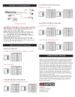
Power Distance Chart
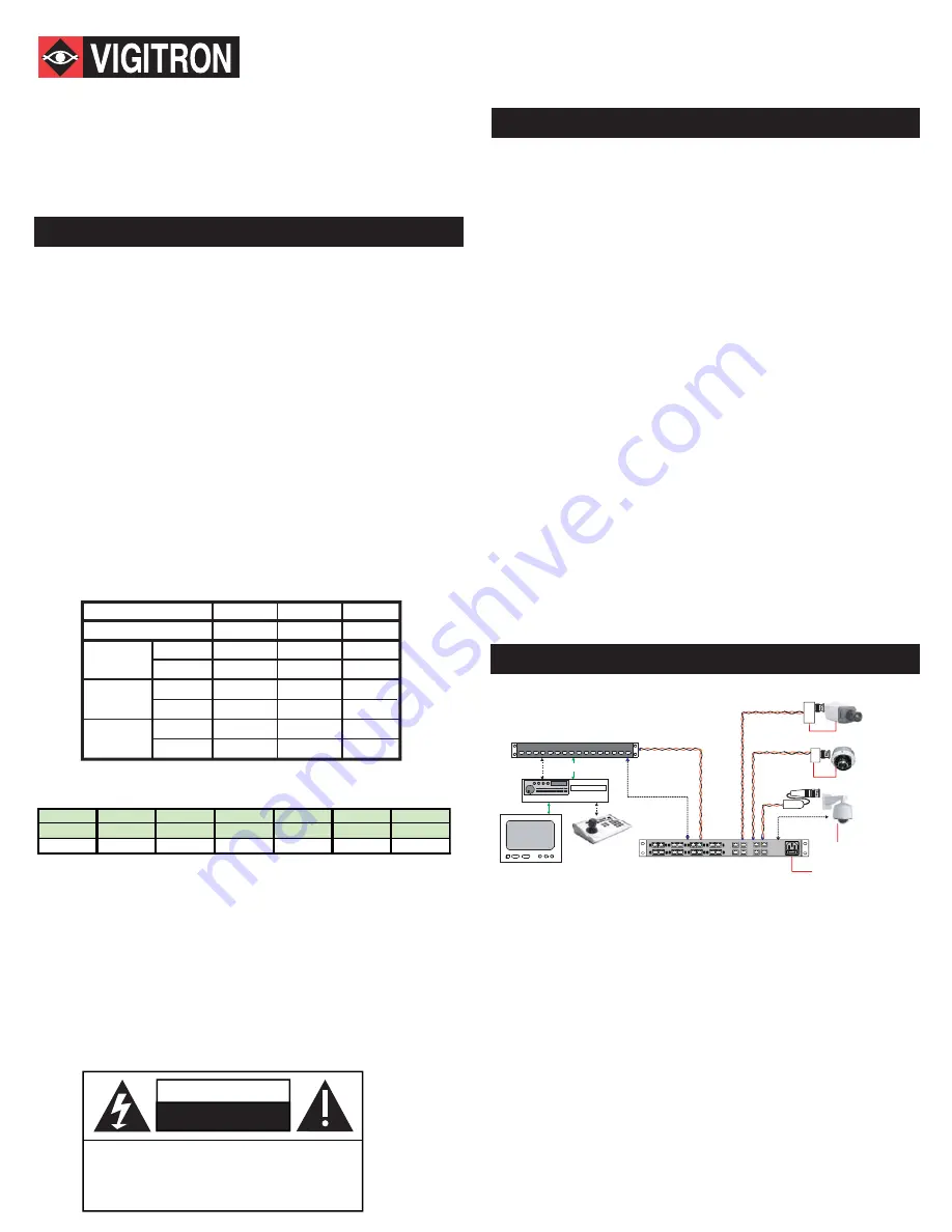
DVR
1053VPD
Vi1416VPD
; 16-Ch Powered VPD Combiner
Cat-5
Cat-5
Data
Data
One Cat5 Cable
per 4 video feeds
Local Power
110/220 VAC
Cat-5
Vi6016HR
16-Ch. Active Receiver
16 Coax Jumpers
1053VPD
1. Use point-to-point Unshielded Twisted Pair wire, 24-16 AWG (0,5-1,3mm),
stranded or solid, Category 2 or better.
2. The Video signal may co-exist in the same wire bundle as other Video,
telephone, Data, control signals, or low-voltage Power. It is also OK to run
Vigitron Video signals in or near electromagnetic fields (in accordance with
National Electrical Code, local, or other local safety requirements).
3. Measure the wire distance.
4. DO NOT USE SHIELDED TWISTED PAIR WIRE. Multi-pair (6 pair or
more) wires with an overall shield are fine.
5. DO NOT USE UN-TWISTED WIRE.
6. DO NOT place a transmit and a receive signal in the same wire bundle. It
may cause interference.
7. DO NOT send “Up-the-Coax” Pan/Tilt/Zoom signals through active
(amplified) Vigitron transmitters or receivers.
Passive Vigitron transceivers can transmit “Up-the-Coax” P/T/Z control
signals up to 750ft (225m).
8. Vigitron recommends the use of 18AWG solid wires for power connections.
Verify wire distance, camera current requirement and wire resistance limit for
the maximum distance that Power can travel. Use “Power Distance Chart” to
verify the wire distance.
AWG
24A W G
22A W G
20A W G 19A W G 18A W G 16A W G
mm
0.5m m
0.6m m
0.7m m
0.8m m
1.0m m
1.3m m
Ohm
52
32
20
16
13
8
.
2
Loop Resistance per 1,000ft (305 m)
Vi1053VPD: Camera End Connection
Video:
Connect the baseband Video signal output of the camera to the BNC
pigtail on the Vi1053VPD.
Power:
Connect the Power UTP pigtail (Black/Red) of the Vi1053VPD to the
power connector of the camera.
Data:
Connect the Data UTP pigtail (Black/White) of the Vi1053VPD to the
data connector of the camera.
Cat-5 Cable:
Connect the RJ-45 connector attached to the camera end of
Cat-5 cable to the RJ-45 Jack of Vi1053VPD. Make sure that the pin-out of
the RJ-45 connector matches the Vigitron color code of the Cat-5 wires.
Application Diagram
Vi1408VPD - Vi1416VPD Application
Technical Wiring Notes
Video-Power-Data CCTV Product Installation Manual
Vi1051VP, Vi1053VPD, Vi1054VP, Vi1508VPD, Vi1516VPD, Vi1408VPD, Vi1416VPD
DO NOT OPEN
RISK OF ELECTRIC SHOCK
CAUTION
CAUTION:
TO REDUCE THE RISK OF ELECTRICAL SHOCK,
DO NOT REMOVE COVER. NO USER SERVISABLE
PARTS INSIDE. REFER SERVICINGTO QUALIFIED
SERVICE PERSONEL.
Important Safety Warning
- This installation should be made by a qualified service person and
should conform to all local codes
- Never put Vigitron signals in the same conduit as high-voltage wiring.
- To reduce a risk of fire or electrical shock, do not expose this product to
rain or moisture
- The Vigitron equipment shall not be exposed to Dripping or splashing.
- No objects filled with liquids, such as vases, shall be placed on Vigitron
equipment.
- The Main 110VAC fuse is 5A. Each camera poer fuse is 2A and can be
accessed by removing the front panel. Fuses may be replaced by a
qualified service person only when the unit is off and AC power cord is
The Vigitron powered VPD series are designed to combine video, PTZ data,
and camera power over a single 4-pair UTP cable to simplify CCTV
instalations in a structured wiring environment. They support up to 16
cameras. These units receive 110/220 VAC power and provide up to 16
ports of 24/28 VAC isolated power to the cameras. Each port is individually
equiped with a 2 A glass fuse that is easily accesibal from front.
Vi1408VPD or Vi1416VPD: Connecting the Control End
Video:
Use a cat-5 cable with RJ-45 connectors on both ends to connect
the RJ-45 video output of the Vi1408VPD or Vi1416VPD to a Vigitron
active or passive receiver HUB.
Power:
Connect the AC power cord to the unit and AC power outlet.
Make sure that the power requirement is in the recommended range.
Important Note: Do not overload the power supply.
Data:
Connect the Data connector of the Vi1408VPD or Vi1416VPD to
the PTZ controlling unit such as DVR.
Camera Cable:
Connect the RJ-45 connector of each Cat-5 cable
coming from cameras to the appropriate RJ-45 jack on Vi1408VPD or
Vi1416VPD. Make sure that the pin-out of the RJ-45 connector matches
the color code of the Cat-5 wires.
For short runs place the Vi1408VPD or Vi1416VPD close to the video
receiver unit at control end. For long runs place the Vi1408VPD or
Vi1416VPD at a mid span point close to the camera end to minimize the
loss of voltage over wisted pair.
Vi1051VP: Camera End Connection
Video:
Connect the baseband Video signal output of the camera to the BNC
pigtail on the Vi1051VP.
Power:
Connect the Power UTP pigtail (Black/Red) of the Vi1051VP to the
power connector of the camera.
Data:
There is no data connection on Vi1051VP.
Cat-5 Cable:
Same as Vi1053VPD.
Vi1054VP: Camera End Connection
Video:
Connect the baseband Video signal output of the camera to the BNC
pigtail on the Vi1054VP.
Power:
Connect the Power UTP pigtail (Black/Red) of the Vi1054VP to the
power connector of the camera. The output of Vi1054VP is regulated 12 VDC
at 600 mA max.
Data:
There is no data connection on Vi1051VP.
Cat-5 Cable:
Same as Vi1053VPD.
Vi1051VP - Vi1053VPD - Vi1054VP Application
Power
Power
Vi1051VP
Vi1054VP


