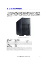
background image


®

®

C  O  M   P  U  T  E  R  S 


 N  E  T  W  O  R  K  S

  S  O  L  U  T  I  O  N  S

M


i


n


d


s

T h i n k


G r e a t

.

.


Viglen VX2000 

Chassis 

User Guide 

Summary of Contents for VX2000

Page 1: ... C O M P U T E R S N E T W O R K S S O L U T I O N S M i n d s T h i n k G r e a t Viglen VX2000 Chassis User Guide ...

Page 2: ...nvironment laboratory To gain a CE mark the Viglen computer range has had to undergo many difficult tests to ensure it is Electromagnetically Compatible These are carried out in the in house Environment lab at Viglen Headquarters We have made every effort to guarantee that each computer leaving our factory complies fully with the correct standards To ensure the computer system maintains compliance...

Page 3: ...by the purchaser for backup Copyright 2005 Viglen Limited All Rights Reserved Viglen VX2000 Server Chassis Version 1 0 Printed in the United Kingdom Liability No warranty or representation either expressed or implied is made with respect to this documentation its quality performance merchantability or fitness for a particular purpose As a result the documentation is licensed as is and you the lice...

Page 4: ... 13 Ultra320 SCSI Backplane Overview 15 3 Chassis Installation and Assembly 19 Opening the Front Bezel 21 Removing the Side Cover 22 Installing Hard Disk Drives and Cages 23 Hotswap Drive Carrier 23 Installing a Hard Drive Carrier to the Hotswap Cage 24 Installing Hard Drives to the Non Hotswap Cage 25 Removing the Hotswap or Non Hotswap Cage 25 Installing the 120mm Fan 26 Installing a 120mm Fan t...

Page 5: ...aching the Add on Card Retainer 31 Releasing the Add on Card Retainer 32 4 Rail Kit Assembly Guide 33 Rail Kit Features 33 Rail Kit Installation 37 5 Chassis Power Supply Technical Data 45 6 Appendices 46 Appendix A Glossary 46 Appendix B Notes 52 Appendix C Suggestions 56 ...

Page 6: ...o purchase an adapter conversion kit The chassis is equipped with power supplies that meet the latest ATX specifications Figure 1 Pedestal and Rackmount Table 1 VX2000 Physical Specifications Specification Pedestal Type Rack Type Height 620mm 220 mm Width 220 mm 425 mm Depth 425 mm 620 mm Weight 27Kg approx 3 5 Bays One 5 25 Bays Three Hard Disk Bays Eight Backplane Support Serial attached SCSI Ul...

Page 7: ...5 bays Houses the CDROM and additional 5 25 devices e g Tape Devices 3 Power Button Powers the server on 4 Reset Button Hard reset of the server 5 Failure Alarm Mute Mutes the redundant PCU alarm Disabled in single PSU systems 6 USB Cover Covers the two USB ports 7 Key lock Locks access to the hot swap hard disk drives stops the removal of the front panel 8 Foot stand Holds up the Server chassis i...

Page 8: ... VX2000 Chassis User Guide 7 Chassis Front Rear and Side Views Chassis Front View without front panel installed Figure 3 Chassis Front View without the Front Panel Chassis Rear View Figure 4 Chassis Rear View ...

Page 9: ...Viglen VX2000 Chassis User Guide 8 Chassis Side View without side panel installed Figure 5 Chassis Side View Without Side Panel Installed ...

Page 10: ...these options see table below Table 3 Chassis Backplane Options Option Cage Option Cage Option 1 Non hotswap cage Non hotswap cage 2 Non hotswap cage Hotswap S ATA cage 3 Non hotswap cage Hotswap SCSI cage 4 Non hotswap cage Hotswap SAS cage 5 Hotswap S ATA cage Hotswap S ATA cage 6 Hotswap S ATA cage Hotswap SCSI cage 7 Hotswap S ATA cage Hotswap SAS cage 8 Hotswap SCSI cage Hotswap SCSI cage 9 H...

Page 11: ...A 2 Backplane Overview Back View Figure 6 SAS SATA 2 Connector s Layout Table 4 SAS SATA 2 Connector s Layout No Description 1 CN2 4 pin DC Power Connector 2 CN1 4 pin DC Power Connector 3 SW1 Front Panel Control Jumper 4 JF2 3P3C Fan Connector ...

Page 12: ...r 9 CN23 7P Serial ATA Connector 10 CN5 Hardware Monitor Switch 11 CN3 External HDD Activity LED connector 12 CN4 HDD Fail LED connector Front View Figure 7 SAS Hard Drive Connector Layout Table 5 SAS SATA 2 Hard Drive Connector Layout No Description 1 CN41 SAS HDD4 connector 2 CN31 SAS HDD3 connector 3 CN21 SAS HDD2 connector 4 CN11 SAS HDD1 connector ...

Page 13: ...r Enabled Disabled 3 Alarm Temperature 65 C 55 C Default Settings CN5 Front Panel Control Jumper Table 7 CN5 Front Panel Control Jumper Pin No Function Pin No Function 1 System Failure LED 2 N A 3 System Failure LED 4 Alarm Mute Switch 5 Key Pin 6 Alarm Mute Switch CN4 Failed HDD LED Table 8 CN4 Failed HDD LED Pin No Function 1 Fail LED for HDD CN11 2 Fail LED for HDD CN21 3 Fail LED for HDD CN31 ...

Page 14: ...Connector s Layout No Description 1 J9 4 pin DC Power Connector 2 J10 4 pin DC Power Connector 3 FAN1 3P3C Fan Connector 4 FAN2 3P3C Fan Connector 5 J5 7P Serial ATA Connector 6 J7 7P Serial ATA Connector 7 J6 7P Serial ATA Connector 8 J8 7P Serial ATA Connector 9 S1 Hardware Monitor Switch 10 JP1 Front Panel Control Jumper ...

Page 15: ...nnector Layout No Description 1 J1 serial ATA HDD1 connector 2 J2 serial ATA HDD2 connector 3 J3 serial ATA HDD3 connector 4 J4 serial ATA HDD4 connector Jumper Settings on the SATA Backplane S1 Hardware Monitor Switch Table 11 S1 Hardware Monitor Switch Configuration No Function ON OFF 1 FAN1 Monitor Disabled Enabled ...

Page 16: ...re 50 C 60 C Default Settings JP1 Front Panel Control Jumper Table 12 JP1 Front Panel Control Jumper Pin No Function Pin No Function 1 System Failure LED 2 System Failure LED 3 GND 4 Alarm Mute Switch 5 N A 6 Alarm Mute Switch Default Settings Ultra320 SCSI Backplane Overview Back View ...

Page 17: ...P3C Connector 10 Terminator connector 4 FAN2 3P3C Connector 11 SW1 HDD1 ID Switch 5 68 pin SCSI Connector 12 SW2 HDD2 ID Switch 6 FAN_DIS FAN Monitor 13 SW3 HDD3 ID Switch 7 J2 HDD Motor Control 14 SW4 HDD4 ID Switch Front View Figure 9 Ultra320 SCSI Hard Drive Connector Layout Table 14 Ultra320 SCSI Hard Drive Connector Layout No Description No Description 1 80 pin SCA Connector 1 3 80 pin SCA Co...

Page 18: ...OFF ON OFF 13 ON OFF ON ON 6 OFF ON ON OFF 14 OFF ON ON ON 7 ON ON ON OFF 15 ON ON ON ON Hard Disk Drive Motor Control J2 Table 16 Hard Disk Drive Motor Control Options Operation Mode P1 P2 P3 P4 P5 P6 Normal Open Open Short Delay Start Short Open Open Remote Start Open Short Open Default Settings Normal Motor spins up at DC power on Delay Start Motor spins up at DC power on after a delay in secon...

Page 19: ...n 65 C Open Open Short Default Settings Fan Monitor Function FAN_DIS Table 18 Fan Monitor Function Monitor Mode FAN1 P1 P2 FAN2 P3 P4 Disabled Short Short Enabled Open Open Default Settings Front Panel Control J3 Table 19 Front Panel Control Pin No Description Pin No Description 1 Alarm LED 2 Alarm LED 3 N A 4 N A 5 Mute Switch 6 Mute Switch ...

Page 20: ...se safety guidelines 1 Turn off all peripheral devices connected to the system 2 Turn off the system by using the push button on off power switch on the front of the system Then unplug the AC power cord from the system or wall outlet 3 Label and disconnect all peripheral cables and all telecommunication lines connected to I O connectors or ports on the back of the system 4 Provide some electrostat...

Page 21: ...fore opening it Otherwise personal injury or equipment damage can result Cautions Electrostatic discharge ESD and ESD protection ESD can damage disk drives boards and other parts We recommend that you perform all procedures in this chapter only at an ESD workstation If one is not available provide some ESD protection by wearing an antistatic wrist strap attached to chassis ground any unpainted met...

Page 22: ...ur system against unauthorised access 1 Insert the key into the security lock and turn it clockwise until it points to the unlock icon as figure 10 2 Press two release button on top of front bezel and the pull it toward you Figure 11 3 Take off the front bezel from chassis body Figure 10 Security Lock Figure 11 Pressing the Front Panel Release Buttons ...

Page 23: ...Refer to the previous section for detailed instructions 2 Loosen the three thumb screws 1 of the side cover Figure 12 Loosening the Thumb Screws 3 Slide the side cover towards you until it is stopped 2 then upwards before taking it off from the chassis body Figure 13 Side cover removal ...

Page 24: ...isk Drive Cages Hotswap Drive Carrier The hard drive carrier is used in the Hotswap cage shown in Figure 14 Figure 15 Hotswap Drive Carrier Table 15 Hard Drive Carrier Features No Description 1 Contact Spring to chassis 2 HDD Power ON LED 3 HDD activity LED 4 Release button 5 Contact spring to upper 6 Lever 7 Air dam must be installed if a hard drive is not present ...

Page 25: ...to the carrier and then secure it with the four screws you can find in the screw bags supplier with each carrier 3 Insert the hard disk carrier into the Hotswap cage with lever still extended See Figure 16 Figure 16 Inserting a Hard Drive Carrier 4 Push the lever back until it clicks into place See Figure 17 Figure 17 Pushing the lever back ...

Page 26: ...s into the cage and align with the mounting holes See Figure 19 3 Secure the hard drives to the drive cage using the screws shown in Figure 18 Figure 19 Mounting Holes on the Drive Cage Removing the Hotswap or Non Hotswap Cage 1 Loosen the four thumbscrews which secure the hard disk drive cage to the chassis body 2 Pull out the hard disk drive cage slightly See Figure 20 Figure 20 Pulling out the ...

Page 27: ...Figure 21 Completely Removing the Cage from the Chassis Installing the 120mm Fan The VIG840 is designed to support three 120mm cooling fans with screw less fan holders There are two fans located in the middle of the chassis and one fan is mounted on the rear panel To secure a fan in the holder follow the below instructions 1 Position a 120mm fan into the hooks of the fan holder See Figure 22 Figur...

Page 28: ... 120mm fan around the frame 3 Finally check that all four hooks of the fan holder have exactly fastened to the fan See Figure 23 Figure 23 Checking the Fan Holder Hooks Installing a 120mm Fan to the VIG840 Chassis 1 Install the 120mm fan to the fan holder See Figure 24 Figure 24 120mm Fan Holder 2 Put the four hooks 1 into specified 120mm fan mounting holes 2 at rear panel or middle panels See Fig...

Page 29: ...840 has a 3 bay to hold a floppy disk drive To install a floppy drive follow the below instructions 1 Loosen the two screws 1 located on the side panel of the floppy disk drive carrier Figure 26 Loosening the Two Screws 2 Insert the hooks shown by arrows in Figure 27 into the mounting holes of the floppy drive ...

Page 30: ... the drive in place with the two screws that were removed earlier Figure 28 Securing the Floppy Drive to the Carrier 4 Insert the drive carrier with the floppy drive installed into the 3 bay until you hear a click sound Figure 29 Installing the Drive Carrier to the Chassis 5 The floppy drive has now been successfully installed ...

Page 31: ...840 chassis 1 Remove a pair of slide rails from the side panel of the drive cage frame Figure 30 Slide Rails 2 Insert both guide pins Circled in Figure 30 on the slide rail into the mounting holes of the CD ROM drive and then secure them in place with screws side by side Figure 31 Securing the Slide Rails to the 5 Device 3 Finally insert the CD ROM into the 5 bay until you hear a click sound ...

Page 32: ... Retainer Detaching the Add on Card Retainer 1 For convenience of installation or cabling the user may want to remove the add on card retainer 2 Push the release button on the top of the add on card holder and then pull it out Figure 33 Release Button on top of the Add on Card Holder 3 Move it upwards slightly and then detach it completely from the chassis body ...

Page 33: ...arrows and rotate the retainer towards you Figure 34 Releasing the Retainer 2 Finally the clamp will be held in the position shown in Figure 35 The user can now install full length PCI cards which will be guided and secured by the holder Once all cards have been installed close the retainer Figure 35 Retainer in Open Position ...

Page 34: ...sis User Guide 33 4 4 R Ra ai il l K Ki it t A As ss se em mb bl ly y G Gu ui id de e Rail Kit Features Figure 36 Side Rail Latch Figure 37 Latch Movement This latch allows for the slide rails to move in both directions ...

Page 35: ...000 Chassis User Guide 34 Figure 38 Outer Rail Release Latch Figure 39 Latch being pulled Towards User This Latch releases the outer rail so that the server can be pushed back into the rack cabinet One direction ...

Page 36: ...table Extension Plate Outer Rail Inner View Rear Location Figure 41 Adjusting the Rear Adjustable Plate This is the rear adjustable extension plate located on the outer rail The rear adjustable extension plate can be adjusted by loosening the screws located on the inner side of the outer rail ...

Page 37: ...ation Figure 43 Ball Bearings located on the Inner Side of the Rail This is the front adjustable extension plate Use the following screws to adjust the length of the rail to fit rack cabinet On the inner side of the rail you have high quality ball bearings which will be used to join the outer rail to the inner rail which is attached to the server ...

Page 38: ...hassis User Guide 37 R Ra ai il l K Ki it t I In ns st ta al ll la at ti io on n Step 1 Attach inner rail to chassis Attach three screws onto the mounting holes located below Figure 44 Attaching Inner Rail to Chassis ...

Page 39: ...Viglen VX2000 Chassis User Guide 38 Step 2 Preparing the outer rail Front Use the screws shown below to extend the outer rail so that it fits your rack cabinet Figure 45 Preparing the Outer Rail front ...

Page 40: ...000 Chassis User Guide 39 Step 3 Preparing the outer rail Rear Loosen the screws below to free the rear plate so that the outer rail can be extended to fit the rack cabinet Figure 46 Preparing the Outer Rail Rear ...

Page 41: ...ng the rack cabinet Firstly insert moveable screw nuts into the square holes on the front and rear sides of the rack cabinet Next screw the rails to the front of the rack cabinet from the inside as shown below Figure 47 Preparing the Rack Cabinet Front ...

Page 42: ...Viglen VX2000 Chassis User Guide 41 Step 5 Secondly attach the rear of the outer rail to the back of the rack cabinet from the outside as shown below Figure 48 Preparing the Rack Cabinet Back ...

Page 43: ...000 Chassis User Guide 42 Step 6 Finally tighten the two screws on the outer rail of the extension plate so that the rail is secure in the rack cabinet Figure 49 Tighten Screws to Secure Rail Kit to Rack Cabinet ...

Page 44: ...t by lining up the outer rails which are now installed in the rack cabinet to the inner rails installed on the sides of the server Once the rails are lined up push the chassis into the rack cabinet until lock position is achieved Figure 50 Installing the Chassis to the Rack Cabinet ...

Page 45: ...be released by the inner rail latch so that the server can be completely pushed into the rack cabinet The arrow below illustrates what direction to move the latch to release the lock Figure 51 Releasing the Inner Rail The Server is now mounted successfully into the rack cabinet ...

Page 46: ...0Vrms or 180 264Vrms 90 132Vrms or 180 264Vrms Frequency Range 47Hz 63Hz 47Hz 63Hz Max input AC Current 10A Max 110Vac 60Hz 5A Max 220Vac 50Hz 12A Max 115Vac 60Hz 6A Max 230Vac 50Hz 3 3V MAX Load 24A 40A 5V Max Load 24A 50A 12V V1 MAX Load 15A 34A 12V V2 MAX Load 15A 12V V3 Max Load 16A 12V V4 Max Load 12A 12V MAX Load 0 5A 1A 5V MAX Load 0 5A 5Vsb MAX Load 2 0A 2A Caution 5V and 3 3V total output...

Page 47: ... which the bits included in a character or block of characters occur during a specific time interval The start of each character block can occur at any time during this interval Contrasts with synchronous AUTOEXEC BAT A special batch file which contains a series of commands that are to be executed when the computer is started up BASIC Beginner s All purpose Symbolic Instruction Code This is a simp...

Page 48: ...g language Cache A small area of high speed memory Cathode Ray Normally referred to as a monitor or VDU Tube CRT Character A symbol on the screen or same as a Byte CMOS Complementary Metal Oxide Semiconductor A logic circuit family that uses very little power COM1 COM2 The names given to the serial communications ports in COM3 COM4 DOS CONFIG SYS A special purpose file which has the configuration ...

Page 49: ... the computer on basic file handling DRAM Dynamic RAM A type of RAM that requires a periodic refresh to maintain data DVD Digital Versatile Disk EMC ElectroMagnetic Compatibility EMI ElectroMagnetic Interference EPROM Erasable Programmable Read Only Memory ESDI Enhanced Small Device Interface which specifies a fast hard disk interface FCC Federal Communications Commission Firmware A program that i...

Page 50: ... I O Input Output Refers to data being sent to or received from a computer K Symbol used to represent Kilobyte which is 1024 bytes KB Abbreviation for Kilobyte i e 1024 bytes Kb Abbreviation for Kilo bit i e 1024 bits Keylock A locking device which can deactivate a keyboard KHz KiloHertz 1000 Hertz LIM Lotus Intel Microsoft Expanded Memory Manager specification LED Light Emitting Diode These are n...

Page 51: ...ystems Interface A multimedia bus and interface specification for fast Hard Disks Tape Backup Units CD ROMs and other Devices SIMM Single In Line Memory Module Software Another name for a computer program SRAM Static RAM Synchronous Transmission of data between devices which are maintaining the same frequency relationship Contrasts with asynchronous TPI Tracks Per Inch TTL Transistor Transistor Lo...

Page 52: ...on specifying EMI suppression Video Computer data or graphics displayed on a monitor or screen W Watt Watt Basic unit of measurement of electrical power Word A number of bits or bytes making up an entity used in the transfer and calculation of data in the computer architecture Word 16 bits 2 bytes long word 32bits 4 bytes ...

Page 53: ...Viglen VX2000 Chassis User Guide 52 Appendix B Notes ...

Page 54: ...Viglen VX2000 Chassis User Guide 53 ...

Page 55: ...Viglen VX2000 Chassis User Guide 54 ...

Page 56: ...Viglen VX2000 Chassis User Guide 55 ...

Page 57: ...en has listed some questions that you may like to answer and return to Viglen This will help Viglen help to keep and improve the standard of their manuals 1 Is the information provided in this and other manuals clear enough 2 What could be added to the manual to improve it 3 Does the manual go into enough detail 4 Would you like an on line version of this manual ...

Page 58: ...port and Service Departments 6 Are there any technological improvements that could be made to the system 1 Other points you would like to mention Please return this slip to Product Development Department Viglen Ltd 7 Handley Page Way Colney Street St Albans Hertfordshire AL2 2DQ ...

Reviews: