
MONTAGEANLEITUNG KONTEC KS
D
INSTALLATION INSTRUCTIONS KONTEC KS
GB
ACHTUNG:
Bei der Montage von Heizkörpern ist zu beachten, dass die Befestigung
von Heizkörpern so dimensioniert wird, dass sie für die bestimmungsgemäße Verwen-
dung und vorhersehbarer Fehlanwendung geeignet ist. Hierbei sind insbesondere
die Verbindung mit dem Baukörper sowie dessen Beschaffenheit, die Geeignetheit
des Montagezubehöres und die möglichen Belastungen nach erfolgter Montage zu
prüfen.
ZU VERWENDENDE AUFHÄNGUNGEN
Hinweis: KS gibt es nur mit aufgeschweißten Laschen.
• Zur Montage der KS sind ausschließlich die Wandaufhängungen WA 10/20 und
WA 11/30 zu verwenden.
• Bei BL 142 bzw. BL 214 muss die Wandaufhängung WA 10/20 verwendet werden.
• Ab einer BL 286 muss die Wandaufhängung WA 11/30 verwendet werden.
MONTAGEHINWEISE FÜR KS
BEI VERWENDUNG DER WANDAUFHÄNGUNG WA 10/20, WA 11/30:
• An den Stirnflächen der Schutzecken die Schrumpffolie öffnen.
• Schutzecken entfernen und den darunterliegenden Karton mittels Tapeziermesser
vorsichtig im Bereich der Aufhängelaschen aufschneiden.
• Befestigung der Wandaufhängung laut Laschenaufschweißbild .
• KS in die Wandaufhängung einhängen und Distanzierung auf die unteren Aufhän-
gelaschen aufstecken.
• KS in horizontaler und vertikaler Richtung ausrichten.
HINWEIS: Die vorgegebene Anschlussposition muss unbedingt
eingehalten werden !!!
Folgende Normen sind bei der Montage der Heizkörper unbedingt einzuhalten:
•
DIN 55900:
Sprühbereich in Nassräumen
•
VDI 2035:
Vermeidung von Schäden in Warmwasserheizungsanlagen
•
DIN 18017 Teil 3:
Lüftung von Bädern und Toiletten ohne Fenster
•
EN 14336:
Heizungsanlagen in Gebäuden, Installationen und Abnahme der Warm-
wasserheizungsanlagen
ATTENTION:
For the correct installation of radiators it is essential that the fixing of
the radiator is carried out in such a way that it is suitable for intended use AND pre-
dictable misuse. A number of elements need to be taken into consideration including
the fixing method used to secure the radiator to the wall, the type and condition
of the wall itself, and any additional potential forces or weights, prior to finalising
installation.
MOUNTINGS TO BE USED
Note: KS available with welded brackets only.
• For fitting the KS only use wall mounting brackets WA 10/20 and WA 11/30.
• With OL 142 or OL 214, the wall mounting bracket WA 10/20 should be used.
• From OL 286, the wall mounting bracket WA 11/30 should be used.
HINTS FOR INSTALLATION OF KS
WHEN USING WALL MOUNTING BRACKET WA 10/20, WA 11/30:
• Open the shrink wrapping on the corner protector front faces.
• Remove the corner protectors and carefully cut the cardboard behind in the area of
the mounting brackets using a wallpaper knife.
• Fit the wall mounting bracket in accordance with the bracket welding diagram.
• Attach the KS to the wall mounting bracket and clip spacers onto the bottom
mounting brackets.
• Align the KS in both horizontal and vertical direction.
NOTE: The connecting position shown must be adhered to !!!
The following standards must be adhered to when installing radiators:
•
DIN 55900:
Spraying area in wet rooms
•
VDI 2035:
Prevention of damage in water heating installations
•
DIN 18017 Part 3:
Ventilation of bathrooms and toilets without windows
•
EN 14336:
Heating systems in buildings. Installation and commissioning of water
based heating systems
KSMA102A
MONTAGEANLEITUNG KONTEC-SENKRECHTHEIZWAND TYPE KS
INSTALLATION INSTRUCTIONS KONTEC VERTICAL HEATING WALL PANEL TYPE KS
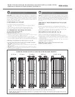
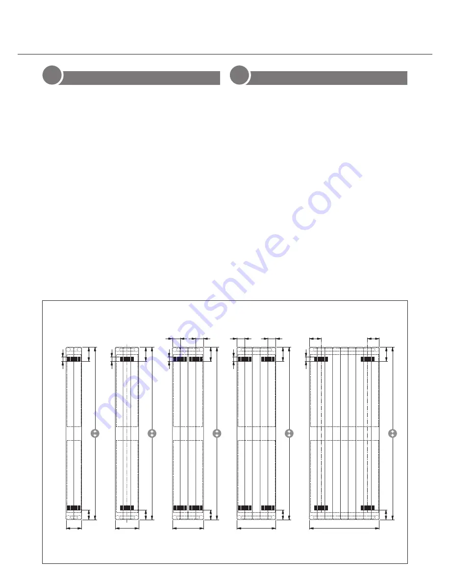
LASCHENAUFSCHWEISSBILD BRACKET / WELDING DIAGRAM
Achtung: Die zulässige Druckstufe (5.0 bzw 8.0 bar) und die zulässige Temperatur (110 °C) sind einzuhalten.
Important: The permissible pressure level (5.0 or 8.0 bar) and the permissible temperature (110 °C) must be adhered to.
60
14
60
14
60
14
142
1000, 1200, 1400, 1600, 1800, 2000, 2200
130
90
40
214
130
90
40
286
130
71
71
90
40
358
130
90
71
71
40
60
48
BL 430 - 862
130
107
107
90
40
1000, 1200, 1400, 1600, 1800, 2000, 2200
1000, 1200, 1400, 1600, 1800, 2000, 2200
1000, 1200, 1400, 1600, 1800, 2000, 2200
1000, 1200, 1400, 1600, 1800, 2000, 2200
BL 142 mm BL 214 mm BL 286 mm BL 358 mm
BL 430 - 862 mm
60
14
60
14
60
14
142
1000, 1200, 1400, 1600, 1800, 2000, 2200
130
90
40
214
130
90
40
286
130
71
71
90
40
358
130
90
71
71
40
60
48
BL 430 - 862
130
107
107
90
40
1000, 1200, 1400, 1600, 1800, 2000, 2200
1000, 1200, 1400, 1600, 1800, 2000, 2200
1000, 1200, 1400, 1600, 1800, 2000, 2200
1000, 1200, 1400, 1600, 1800, 2000, 2200
BL 142 mm BL 214 mm BL 286 mm BL 358 mm
BL 430 - 862 mm


