background image


Itona TC63yy 

Hardware User Guide 

Summary of Contents for Itona TC63yy

Page 1: ...Itona TC63yy Hardware User Guide...

Page 2: ...Every effort has been made to make this guide as complete and as accurate as possible but no warranty or fitness is implied The authors and the publisher shall have neither responsibility nor liabilit...

Page 3: ...which can be determined by turning the equipment Off and On the user is encouraged to try to correct the interference by one or more of the following measures Re orient or relocate the receiving ante...

Page 4: ...ii Regulatory Certifications...

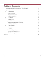
Page 5: ...uide 1 Abbreviations and Acronyms 2 Chapters in the Manual 2 2 Installation 4 Unpacking the Unit 4 Preparing to Connect 4 Connecting the Accessories and Power Supply 5 Connecting to the Server 7 3 Spe...

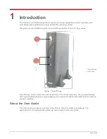
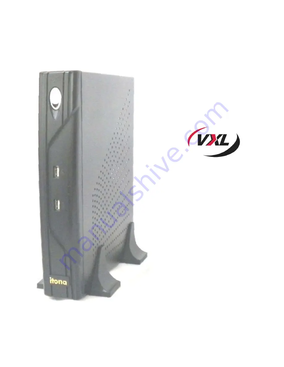
Page 6: ...63yy series Figure 1 ItonaTC63yy Itona TC63yy deliver smart and robust solutions for Thin Client computing They are aesthetically and ergonomically designed compact desktop Itona series thin clients o...

Page 7: ...to set up the hardware 3 Specifications Contains hardware mechanical electrical interface and operating environment specifications 4 Troubleshooting Contains solutions to problems that you may encount...

Page 8: ...nsure that all expansion slots on the back or side of the client are covered with metal retaining brackets and tightly attached to the computer cabinet Only equipment certified to comply with Class B...

Page 9: ...acket single side Hardware Installation Guide Ensure that all the contents mentioned above are in the carton Contact the dealer or reseller from whom you have purchased the product if any of those are...

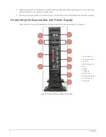
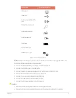
Page 10: ...nches 5 cm on all sides of the unit for efficient convection cooling Connecting the Accessories and Power Supply The various connectors available on the rear panel of the client are shown in Figure 2...

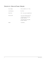
Page 11: ...wer supply 1 Connect the DVI cable from your display unit to the DVI I port 2 Connect the USB devices to the USB ports 3 Connect the external powered speakers to the audio output LINE OUT port 4 Conne...

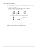
Page 12: ...a 10 100 1000 cable to the Ethernet LAN port of the client 2 Connect the other end to a LAN hub as shown in Figure 3 Figure 3 LAN Connection through TCP IP 3 Press the power button to switch on the I...

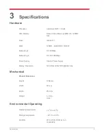
Page 13: ...33 667 Networking1 10 100Mbps Networking 2 10 100 1000Mbps Power Supply Internal Power Supply Display Resolution 16 32 Bits 1920x1200 60Hz max Mechanical Product Dimension Height 1268mm Width 50 mm De...

Page 14: ...apter Line Voltage 100V to 240V AC 6 10 Line Frequency 50 60 Hz Power Inlet 1 2A 3 pin power plug IEC 320 Power Oulett 3 pin power socket IEC 320 For devices upto 0 30A max 100VAC 50 60Hz For devices...

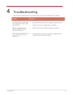
Page 15: ...t is switched on Ensure that the power cord is plugged into an AC outlet Check the fuse in the power plug if available There is no display on the monitor though the power indicating LED glows Ensure t...

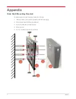
Page 16: ...install single side wall mounting bracket for TC63yy 1 Drill four holes on the wall and insert four M7x33 wall plugs 2 Place Single Side Wall Mounting Bracket 3 Fix the four M4x24 self taped screws 4...

Page 17: ...compatible operating at 115 2K baud maximum Pin Signal Description 1 DCD Data Carrier Detect 2 RxD Receive Data 3 TxD Transmit Data 4 DTR Data Terminal Ready 5 GND Signal Ground 6 DSR Data Set Ready 7...

Page 18: ...CT 14 AFD 15 ERROR 18 25 GROUND 10 100 1000 Ethernet LAN Port RJ 45 modular 8 pin jack 10 100 1000 Mbps Video Port 15 pin D type female connector Pin Signal Pin Signal Pin Signal 1 Red 6 Red return GN...

Page 19: ...No Connection 15 No Connection Mouse keyboard Port PS 2 Mouse Keyboard connector Pin Signal Pin Signal 1 Mouse Keyboa rd data 4 VCC 2 NC 5 Mouse Keyboard clock 3 GND 6 NC Audio Microphone Port Standa...

Page 20: ...pin D type connectors for RS232 connections In order to connect an RS232 device with a 25 pin connector 9 pin connector signals must be converted to 25 pin connector signals as shown in the following...

Page 21: ...the pin connections of the Standard Centronics parallel cable Some manufacturers change pin functions or polarity on their printers For such printers custom cables may be necessary Refer to your print...

Reviews: