background image

USER MANUAL

This manual does not include all of the details of design, production, or variations of the equipment. Nor does it cover every possible
situation which may arise during installation, operation or maintenance.
The information provided in this manual was deemed accurate at the publication date.

Www.prolight.co.uk

Active Professional Two-Way

Sound Reinforcement Loudspeaker

audi

PSR-15A

Summary of Contents for PSR-15A

Page 1: ...of the equipment Nor does it cover every possible situation which may arise during installation operation or maintenance The information provided in this manual was deemed accurate at the publication date Www prolight co uk Active Professional Two Way Sound Reinforcement Loudspeaker audi PSR 15A ...

Page 2: ...diators heat exchangers stoves or otherap paratus that produceheat 9 Please ensurethat this apparatusis correctly earthed at alltimes 10 Protectthe power cordfrom being walkedon or trapped particularly atplugs and thepoint where they exitfrom the apparatus 11 Only useattachments accessories specified by the manufacturer 12 Use onlywith a cart stand bracket ortable specified by themanufacturer or s...

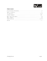
Page 3: ...on Manual Table of Contents Important Safety Instructions 2 Table of Contents 3 I n t r o d u c t i o n 4 5 Hookup Diagrams 6 7 Rear Panel Description 8 Block Diagram 8 S p e c i f i c a t i o n s 9 1 0 N o t e s 1 1 ...

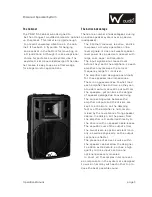
Page 4: ...nuous before clipping Each amplifier has its own compressor circuit that acts when the input signal is large enough to cause clipping disto rtion and excessive voice coil heat The compressor will automatically decrease the input signal to a safe level The compressor in the low frepuency amp works independently from that in the high frequency amp The low frequency amp uses servo feed back loop whic...

Page 5: ...lifier only receives the correct frequency range for its driver The amplifiers are designed specifically for these speaker load impedances There is no guesswork as to what load each amplifier has to drive so they can provide maximum acoustic output from the speakers yet minimize the danger of speaker damage due to overdriving The connecting wires between the amplifier outputs and the drivers are k...

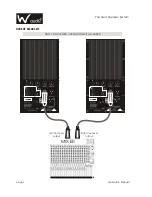
Page 6: ...MIXER page 6 Operation Manual HOOKUP DIAGRAMS Powered Speaker System PSR 15A STEREO OPERATION WITH A MIXER Left Line level output Right Line level output ...

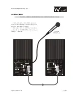
Page 7: ...PSR 15A USING A MICROPHONE AND THE THRU CONNECTION For microphone connections you can daisy chain up to two PSR 15A using the MIX OUTPUT jacks as shown Take great care to point any microphon es away from the otherwise you may get feedback PSR 15A Dynamic Microphone ...

Page 8: ...LINE INPUT MIX OUTPUT MIX OUTPUT EQ EQ MUSIC ENGINE MUSIC ENGINE Treble clip Bass clip Active Indicator Microphone Input 1 Microphone Volume 1 Microphone Input 2 Microphone Volume 2 Voltage Selector Grounded Screw Bass Control Treble Control Line Volume Control Master Volume Control Line Input Jack Mix Input Jack Power Switch IEC Socket Fuse 10 11 12 13 14 15 16 17 18 1 2 3 4 5 6 7 8 9 ...

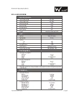
Page 9: ...THD Cooling Design Rated Power Rated THD Cooling Design 350 watts 0 1 Convection Extrusion Class G 50 watts 0 1 Convection Extrusion Class AB Power Amplifiers Low Frequency Power Amplifier Hi Frequency Power Amplifier Rated power iscontinuous rms wattageinto transducer srated impedance 1kHz for theHF amplifier and 100 Hz for the LFamplifier Transducers Low Frequency Transducer Diameter Voice Coil ...

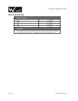
Page 10: ... 30kg Disclaimer Since we arealways striving tomake our productsbetter by incorporatingnew and improvedmaterials components and manufacturing methods we reserve the rightto change thesespecifications at anytime without notice PSR 15A SPECIFICATIONS Powered Speaker System page 10 Operation Manual ...

Page 11: ...page 11 Operation Manual NOTES Powered Speaker System ...

Page 12: ......

Reviews: