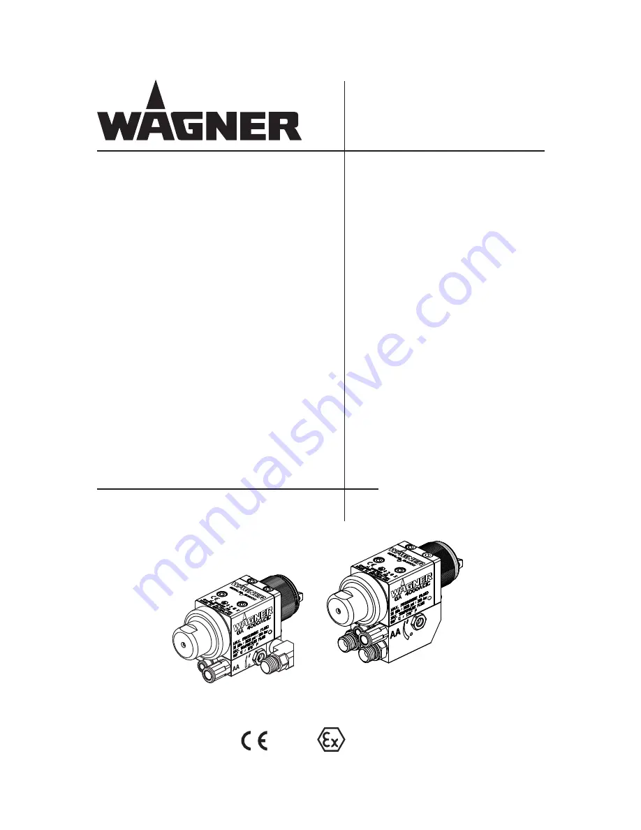
background image

II 2GX (Atex 95)


GA 4000ACIC-R
GA 4000ACIC-S

B_03045

AirCoat
Automatic spray gun

Edition 06/ 2011

Translation of the original 
Operating manual

Summary of Contents for GA 4000ACIC-R

Page 1: ...II 2GX Atex 95 GA 4000ACIC R GA 4000ACIC S B_03045 AirCoat Automatic spray gun Edition 06 2011 Translation of the original Operating manual ...

Page 2: ......

Page 3: ...tion identification 9 2 4 3 X Special notes 9 2 4 4 Safety instructions 9 3 GUARANTEE AND CONFORMITY DECLARATIONS 10 3 1 Important notes on product liability 10 3 2 Guarantee claim 10 3 3 CE Conformity 11 3 4 National technical specifications 11 4 DESCRIPTION 12 4 1 Field of application using in accordance with the instructions 12 4 1 1 Processable materials 12 4 2 Delivery scope 12 4 2 1 Type des...

Page 4: ...pray gun 28 5 3 2 Preparation for starting up 29 5 4 Works 30 5 4 1 Start up for spraying AirCoat 30 5 4 2 Adjusting the spray pattern 30 5 4 3 Changing AirCoat nozzle 31 5 4 4 Cleaning AirCoat nozzle 31 5 4 5 Eliminate nozzle clogging 32 5 4 6 Exchange of round jet nozzle insert 33 6 MAINTENANCE 34 6 1 Shutting down and cleaning 35 6 2 Replacing the paint hose 36 6 3 Replacing the nozzle seal 36 ...

Page 5: ...r preventing the hazard and its consequences This operating manual contains information on the operation repair and maintenance of the unit Always observe these instructions when operating the unit This equipment can be dangerous if it is not operated in accordance with this manual Compliance with these instructions constitutes an integral component of the warranty agreement This operating manual ...

Page 6: ... work is commenced on active parts Inform staff about planned work observe electrical safety regulations NSURE THAT THE UNIT IS OPERATED AND REPAIRED ONLY BY TRAINED PERSONS Make sure that the floor in the area where you are working is derivable in accordance with EN 61340 4 1 Ensure that all persons within the working area wear derivable shoes Ensure that during spraying persons wear derivable glo...

Page 7: ...tely Avoid danger of injury through recoil forces Ensure that you have a firm footing when operating the spray gun Only hold the spray gun briefly in any one position Depending on the electrostatic charge and the flow speed of the spray an electrostatic charge may occur in the equipment This could cause a spark or flame on discharging Ensure that the unit is earthed for every spraying operation Earth ...

Page 8: ...solvents and cleaning agents being used Take the specified protective measures in particular wear safety goggles protective clothing and gloves as well as hand protection cream if necessary Use a mask or breathing apparatus if necessary For sufficient health and environmental safety Operate the unit in a spray booth or on a spraying wall with the ventilation extraction switched on Wear suitable prot...

Page 9: ...mperature corresponds to the permissible material temperature This and the permissible ambient temperature can be found in the Technical Data 3AFE HANDLING OF 7 2 SPRAY UNITS ECHANICAL SPARKS CAN FORM IF THE UNIT COMES INTO CONTACT WITH METAL N AN EXPLOSIVE ATMOSPHERE O NOT KNOCK OR PUSH THE UNIT AGAINST STEEL OR RUSTY IRON O NOT DROP THE SPRAY GUN 5SE ONLY TOOLS THAT ARE MADE OF A PERMITTED MATER...

Page 10: ...antee for damage that has been caused or contributed to for the following reasons Unsuitable or improper use faulty installation or commissioning by the purchaser or a third party normal wear negligent handling defective maintenance unsuitable coating products substitute materials and the action of chemical electro chemical or electrical agents except when the damage is attributable to us Abrasive...

Page 11: ...ing with liquid ejection devices c BGR 104 Explosion Protection Directive d TRBS 2153 Avoiding ignition risks e BGI 740 Painting rooms and equipment f ZH 1 406 Guidelines for liquid ejection devices Note All titles can be ordered from Heymanns Publishing House in Cologne or they are to be found in the Internet Herewith we declare that the supplied version of AirCoat Automatic spray gun GA 4000ACIC...

Page 12: ...r controlled via valve within gun EC Shaping and atomizing air controlled via valve outside of gun 4 2 DELIVERY SCOPE Top coat paints primer paints corrosion protection solvents textured paints lyes staining solvents clear paints separating fluid etc on a solvent or water basis Note In the event of application problems contact your WAGNER branch and the paint manu facturer 4 2 1 TYPE DESCRIPTION 4...

Page 13: ...ble 4 2 3 Basic versions Automatic gun GA 4000ACIC 4 2 4 6 supplementary components Air connections 4 2 4 4 Supplementary components Nozzle round 4 2 4 3 Supplementary components Nozzle flat 4 2 4 7 Supplementary components Material connections 4 2 4 5 Supplementary components Lock pin 4 2 4 2 Supplementary components Air caps 4 2 2 OVERVIEW 8 4 Accessories Holders 4 2 4 1 Supplementary components...

Page 14: ... Operating manual in the local language With the accessory components the basic execution of the automatic gun can be harmonised and supplemented depending upon requirements and accessory desires optimally on each application case The delivery note shows the exact scope of delivery 4 2 3 STANDARD VARIANT 4 2 4 SUPPLEMENTARY COMPONENTS 4 2 4 1 GROUND PLATE Part No Description 2308810 Ground plate G...

Page 15: ...us blue for high viscosity paints 2308808 Air cap LV plus red for low viscosity paints 2313493 Air cap LA plus bronze Part No Description 379XXX For a nozzle list look in chapter 8 Part No Description 379XXX For a nozzle list look in chapter 8 4 2 4 4 AIRCOAT ROUND JET NOZZLE ACR3000 4 2 4 3 AIRCOAT FLAT JET NOZZLE ACF3000 4 2 4 2 AIR CAPS ...

Page 16: ... in screw connection straight ø 6 mm 1 8 ø 0 24 inch 1 8 Standard 9998993 Screw in screw connection straight ø 8 mm 1 8 ø 5 16 1 8 Part No Description 2310534 Lock pin assy 4 2 4 6 AIR CONNECTIONS 4 2 4 7 LOCK PIN Part No Description 350550 Connection nipple straight 2314065 Connection nipple 90 4 2 4 5 MATERIAL CONNECTIONS ...

Page 17: ...l connection internal thread Inch G1 4 Air connection internal thread Inch G1 8 Weight basic version g oz 880 31 Maxi temperature material o C o F 80 176 Maxi temperature air o C o F 50 122 Maxi ambient temperature o C o F 5 40 41 104 Sound level at 0 3 MPa 3 bar 43 5 psi air pressure and 11 MPa 110 bar 1549 psi material pressure dB A 82 0 A rated sound pressure level measured at 0 5 m distance ac...

Page 18: ...5 C 77 5 3 05 D 55 2 17 E 18 0 1 0 71 0 004 F 18 0 1 0 71 0 004 OPERATING MANUAL EDITION 06 2011 PART NO DOC2312956 4 3 2 MEASUREMENTS AND CONNECTIONS Connection data Ground plate to GA 4000ACIC R CA G1 8 6 mm 0 24 inch control air AA G1 8 8 mm 0 31 inch atomizing air M G1 4 NPS1 4 material ...

Page 19: ...RATING MANUAL EDITION 06 2011 PART NO DOC2312956 Metals Plastic Hard metal UHMW PE Stainless steel 1 4310 PTFE Stainless steel 1 4305 FPM Stainless steel 1 4104 POM PA 6 6 EPDM 4 3 3 MATERIALS OF PAINT WETTED PARTS Connection data Ground plate to GA 4000ACIC S CA G1 8 6 mm 0 24 inch control air AA G1 8 8 mm 0 31 inch atomizing air M G1 4 NPS1 4 material ...

Page 20: ...hannel The device consists of a gun head A gun body B the drive C and a base plate D At the gun head A is cultivated the air cap G the appropriate nozzle H and diverse sections for the sealing and attachment In the gun head A the material valve and the packing are accommodated In the gun body B the clamping mechanism for the packing is inserted The gun body serves besides as connecting piece betwe...

Page 21: ...is position the coating material which is under pressure is applied to the workpiece Nozzle 4 4 3 FUNCTIONS OF THE SPRAY GUN 4 4 2 MODE NC AND C 4 4 2 2 MODE C WITH MATERIAL CIRCULATION In this mode of operation the locking pin M must be removed from the left or right material channel in the gun head A Screw on additional connection fitting J The material entrance ME and the material return MR are...

Page 22: ...izing air and so that they influence each other during adjustment The material connections and the colour channels in the base plate are arranged so that several guns can be used in circulation operation 4 5 SPRAYING PROCESS Variable spray jet width Atomizing air In the AirCoat process high pressure of 3 15 MPa 30 150 bar 435 2176 psi is used to atomize the material A soft flat spray is achieved w...

Page 23: ... be adjusted by turning the nozzle nut Themulti channelswirlnozzleproducesfinepaintparticles whileatthesametimereducing their forwards speed and swirling them to produce a rotating motion The result is a soft extremely well atomized spraying cloud Nozzle nut Spray jet Multi channel swirl nozzle AirCoat Air Spray material AirCoat Air Advantages High painting capacity Low fogging tendency Good finis...

Page 24: ...ray booth E Automatic movement system F Paint supply G Detection of part H Spray guns I Supply air system and exhaust air system The pray gun must be used a part of an spraying system The spraying system shown in the figure is only one example Contact your Wagner distributor for assistance in designing a system to meet your needs Theoperatinginstructionsandthesafetyregulationsfortheadditionalsyste...

Page 25: ...ventilation extraction switched on Observe national and local regulations for the outgoing air speed SIHI_0028_GB CAUTION Impurities in the spraying system Spray gun blockage materials harden in the spraying system Flush the spray gun and paint supply with a suitable cleaning agent SIHI_0001_GB SIHI_0029_GB DANGER Bursting hose bursting threaded joints Danger to life from injection of material Ens...

Page 26: ...azard from electrostatic sparks or flames Earth all unit components Earth the workpieces being painted SIHI_0027_GB Any material containers and the unit must be connected by a potential equalisation earth cable WARNING Heavy paint mist if earthing is insufficient Risk of poisoning Insufficient paint application quality Earth all unit components Earth the workpieces being painted SIHI_0003_GB ...

Page 27: ...240 240 2 4 56 65 260 260 2 6 62 68 280 280 2 8 65 70 300 300 3 70 74 320 320 3 2 340 340 3 4 360 360 3 6 80 380 380 3 8 400 400 4 90 OPERATING MANUAL EDITION 06 2011 PART NO DOC2312956 5 2 1 VISCOSITY CONVERSION TABLE The viscosity of the paints is of great importance The best results are obtained for paints of 80 and 150 mPas Processing of up to 260 mPas is generally possible without problem if ...

Page 28: ... work on the unit in the event of work interruptions and functional faults Switch off the energy compressed air supply Relieve the pressure from the spray gun and unit Secure the spray gun against actuation By functional faults Identify and correct the problem proceed as described in chap Trouble shooting SIHI_0064_GB CAUTION Solvent in air conduit Problems By cleaning the spraygun use with min 0 ...

Page 29: ...tly see flat side X Fit the air cap nut and tighten by hand 4 Connect control air hose and atomizing air hose to spray gun and to oil free dry air supply with regulator 5 Visually check the permissible pressures for all the system components 6 Make sure that the unit and all other conductive parts within the work area are earthed 7 Set material pressure 10 MPa 100 bar 1450 psi and use a suitable m...

Page 30: ...llustration Note Repeat point 4 and 5 until the optimum spray pattern is reached process iterative Spray pattern No shaping air atomizing air Too little shaping air atomizing air Correct amount of shaping air of atomizing air 5 4 2 ADJUSTING THE SPRAY PATTERN The spray pattern can be adjusted to suit the object being sprayed using the shaping air throttle valve The illustration showstheinfluenceof...

Page 31: ...ctly see flat side X 8 Fit the union nut A and tighten by hand For disassembly and assembly see AirCoat nozzles section 5 4 3 The AirCoat nozzle C can be placed into a cleaning solvent which has been recommended by the paint manufacturer CAUTION Defective AirCoat nozzle Insufficient paint application quality Do not use sharp edged objects to treat hard metal on the AirCoat nozzle SIHI_0020_GB CAUTI...

Page 32: ...ssure back on 9 Spraying Connect control air hose 10 When the blockage has been flushed out secure the spray gun 11 Relieve the pressure of gun and unit 12 Secure gun Remove the control air hose 13 Screw off the union nut A 14 Remove air cap B and reverse AirCoat nozzle C by hand again Nozzle and nozzle seal clean and to nozzle in spraying position the nozzle seal D put on 15 Refit air cap B on th...

Page 33: ...ove nozzle insert B with nozzle spanner A 4 Fit the new nozzle insert in reverse order see chapter 8 3 Note Cleaning of clogged round jet nozzle 1 By means of nozzle spanner A loosen nozzle insert B by a half turn 2 Remove the nozzle spanner and press the gun briefly 3 After cleaning the nozzle re tighten the nozzle insert 5 4 6 EXCHANGE OF ROUND JET NOZZLE INSERT ...

Page 34: ...SIHI_0001_GB CAUTION Cleaning agent in the air duct Functional faults caused by swollen seals Never immerse the spray gun in cleaning agent SIHI_0066_GB SIHI_0004_GB WARNING Incorrect maintenance repair Risk of injury and damage to the equipment Repairs and part replacement may only be carried out by specially trained staff or a WAGNER service center Before all work on the unit and in the event of...

Page 35: ...ntrol air hose 8 Cleanexternalthespraygunwithacleaningagentrecommendedbythemanufacturer and dry with a cloth or blow gun SIHI_0064_GB CAUTION Solvent in air conduit Problems By cleaning the spraygun use with min 0 05 MPa 0 5 bar 7 25 psi shaping air Cleaning solvent must not get into the air ducts DANGER Exploding gas air mixture Danger to life from flying parts and burns Never spray into a closed ...

Page 36: ...h and unscrew material hose 6 Assembly Fit material hose by hand and tighten with 2 open ended wrenches 1 Finishing work and cleaning 2 Relieve the pressure of gun and unit 3 Secure gun Remove the control air hose 4 Screw off the union nut A 5 Remove air cap B and nozzle C 6 Release the nozzle seal D with the help of a screwdriver 7 Fit new nozzle seal to valve housing E 8 Assemble in reverse orde...

Page 37: ...and the nozzle Counter hold with socket spanner size 13 mm 0 51 inch Note The sealing nipple E can be unscrewed from the nozzle housing using a small eye wood bolt pushed into it Nozzle spanner D Part No 128901 Remove with pin Ø 1 5 mm 0 06 inches CAUTION Defective nozzle body Poor spray pattern Handle the nozzle body A with care SIHI_0042_GB ...

Page 38: ...EPLACING PARTS OF THE GUN BODY 6 5 1 DISMANTLING GA 4000ACIC Note Circulation mode without lock pin Note Base plate assy B must not dismounted CAUTION Defective plunger shaft Packing leaks Greater wear on the packing Handle the plunger shaft K with care The plunger shaft has the function of a sliding surface SIHI_0043_GB ...

Page 39: ...66 M5 SW 3 0 12 inch SW 12 0 47 inch F OPERATING MANUAL EDITION 06 2011 PART NO DOC2312956 Blow gun Note Pull the damaged seal F out using a pliers Note Stuck components can be pushed out with a drift maxi Ø 3 mm 0 12 inch ...

Page 40: ... EDITION 06 2011 PART NO DOC2312956 6 5 2 RE ASSEMBLE GA 4000ACIC General note Lightly greased o rings and sliding surfaces with vaseline white PHV II Note Put the seal G on the Air cap H and place seal and air cap into gun housing Screw union nut K in as far as the seal ring in the groove catches Snap hearable ...

Page 41: ...1 GA 4000ACIC B_03068 M5 SW 3 mm 0 12 inch 4 Nm 2 95 lbft SW 12 0 47 inch 10 Nm 7 38 lbft OPERATING MANUAL EDITION 06 2011 PART NO DOC2312956 Dismount union nut and air cap Dismount union nut and air cap ...

Page 42: ...h 5 4 1 Nozzle too large Select smaller nozzle see paragraph 8 1 Material pressure too low Increase pressure at pump Material viscosity too high Thin material in accordance with the manufacturer s instructions Partial nozzle blockage Nozzle cleaning see paragraph 5 4 5 Wrongly adjusted shaping air Readjust shaping air Air cap faulty blocked holes damaged seal Clean or replace air cap Wrong air cap...

Page 43: ...43 GA 4000ACIC OPERATING MANUAL EDITION 06 2011 PART NO DOC2312956 ...

Page 44: ...15 15 10 0 015 0 38 100 379215 15 20 0 015 0 38 200 379315 15 30 0 015 0 38 300 379415 15 40 0 015 0 38 400 379515 15 50 0 015 0 38 500 379615 15 60 0 015 0 38 600 379815 15 80 0 015 0 38 800 379217 17 20 0 017 0 43 200 379317 17 30 0 017 0 43 300 379417 17 40 0 017 0 43 400 379517 17 50 0 017 0 43 500 379617 17 60 0 017 0 43 600 379817 17 80 0 017 0 43 800 OPERATING MANUAL EDITION 06 2011 PART NO...

Page 45: ... 0 025 0 64 600 379825 25 80 0 025 0 64 800 379427 27 40 0 027 0 69 400 379627 27 60 0 027 0 69 600 379827 27 80 0 027 0 69 800 379429 29 40 0 029 0 75 400 379629 29 60 0 029 0 75 600 379829 29 80 0 029 0 75 800 379431 31 40 0 031 0 79 400 379631 31 60 0 031 0 79 600 379831 31 80 0 031 0 79 800 379435 35 40 0 035 0 90 400 379635 35 60 0 035 0 90 600 379835 35 80 0 035 0 90 800 OPERATING MANUAL EDI...

Page 46: ...nsert R15 15 approx 250 9 84 132725 Nozzle insert R16 16 approx 250 9 84 132726 Nozzle insert R17 17 approx 250 9 84 132727 Nozzle insert R18 18 approx 250 9 84 132728 Nozzle insert R19 19 approx 250 9 84 132729 Nozzle insert R20 20 approx 250 9 84 132730 Nozzle insert R21 21 approx 250 9 84 132731 Nozzle insert R22 22 approx 250 9 84 Jet width in mm inches at a distance of 30 cm 11 8 inches from ...

Page 47: ...Pa 270 bar 3916 psi 9982035 Air hose red A ø 6 mm AD 0 24 inch I ø 4 mm ID 0 16 inch polyamide order by the meter 9982061 Air hose blue A ø 6 mm AD 0 24 inch I ø 4 mm ID 0 16 inch polyamide order by the meter 9982033 Air hose green A ø 6 mm AD 0 24 inch I ø 4 mm ID 0 16 inch polyamide order by the meter 9982062 Air hose blue A ø 8 mm AD 0 32 inch I ø 5 5 mm ID 0 22 inch polyamide order by the mete...

Page 48: ...G MANUAL EDITION 06 2011 PART NO DOC2312956 Part No Description 2314079 Adapter plate Cefla 380942 Gun holder turnable standard 380945 Gun holder turnable 40 40 5 380943 Swivel drive assy 380944 Cross attaching piece for swivel drive ...

Page 49: ... work Always supply the following information to ensure delivery of the right spare part Part Number description and quantity The quantity need not be the same as the number given in the Quantity column This number merely indicates how many of the respective parts are used in each sub assembly The following information is also required to ensure smooth processing of your order Address for the invo...

Page 50: ...8 29 31 30 32 39 19 20 P_03070 33 34 11 1 Nm 0 74 lbft Locite 243 1 2 25 Nm 18 44 lbft 25 Nm 18 44 lbft 10 Nm 7 38 lbft 37 37 4 Nm 2 95 lbft 21 3 Nm 2 21 lbft 3 40 41 42 43 OPERATING MANUAL EDITION 06 2011 PART NO DOC2312956 9 2 SPARE PARTS LIST GA 4000ACIC Special version in EPDM ...

Page 51: ...ead piece 14 2 9974153 O ring 15 1 367528 O ring 16 1 2313516 Packing standard 16a 1 2321376 Packinginsert GA 4000AC longlife 17 1 2314277 Piston housing IC 18 4 2308292 Cheese head screw 19 1 2310534 Lock pin material channel assy 20 1 2307873 O ring 21 1 2307739 Mounting nut 22 1 2307868 Round spray jet reducing 23 1 9971388 O ring 24 2 2310473 Sealing material 25 5 9974265 O ring 26 1 9998993 S...

Page 52: ...Base plate GA 4000ACIC 23 24 25 2322532 Seals set GA 4000ACIC EPDM 40 41 42 Pos K Qty Bestell Nr Description 34 1 9971025 O ring 35 1 2314275 Piston IC assy 36 1 2314273 Valve rod IC assy 37 1 9992698 Vaseline white PHHV 38 1 9998991 Screw spring 39 1 2314242 Ground plate GA 4000ACIC R 40 1 2322531 Piston seal EPDM 41 1 2322530 O ring 42 1 9974179 O ring 43 1 2322532 Seals set GA 4000ACIC EPDM Wea...

Page 53: ...53 GA 4000ACIC OPERATING MANUAL EDITION 06 2011 PART NO DOC2312956 ...

Page 54: ...les wagner france fr Netherlands WSB Finishing Equipment B V De Heldinnenlaan 200 NL 3543 MB Utrecht Telephone 31 0 30 241 4155 Telefax 31 0 30 241 1787 E Mail info wsb wagner nl HP www wsb wagner eu Italy WAGNER COLORA S r l Via Fermi 3 I 20875 Burago di Molgora MB Telephone 39 039 625021 Telefax 39 039 6851800 E Mail info wagnercolora com Japan WAGNER Spraytech Ltd 2 35 Shinden Nishimachi J Dait...

Page 55: ......

Page 56: ...RMANY 7 2 MB TTO ILIENTHAL 3TR 0OSTFACH ARKDORF 4ELEPHONE 4ELEFAX AIL SERVICE STANDARD WAGNER GROUP COM 3WITZERLAND 7 2 NDUSTRIESTRASSE 0OSTFACH LTSTËTTEN 4ELEPHONE 4ELEFAX AIL REP CH WAGNER GROUP CH WWW WAGNER GROUP COM 2312956 ...

Reviews: