background image


0102

II 2D 2mJ

P_01660

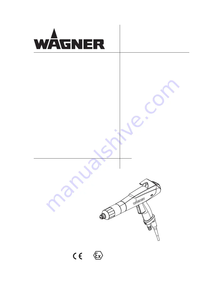
Manual Powder Spray Gun

PEM-X1

Version 09/2012

Translation of the Original 
Operating Manual

Summary of Contents for PEM-X1

Page 1: ...0102 II 2D 2mJ P_01660 Manual Powder Spray Gun PEM X1 Version 09 2012 Translation of the Original Operating Manual...

Page 2: ......

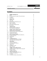
Page 3: ...2 Personnel Qualifications 11 4 1 3 A Safe Work Environment 11 4 2 Safety Instructions for Staff 12 4 2 1 Safe Handling of WAGNER Powder Spray Devices 12 4 2 2 Grounding the Device 12 4 2 3 Material H...

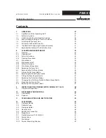
Page 4: ...ocedures 36 8 2 4 Replacing the Spray Gun 37 8 3 Removing the Flat Spray Nozzle 38 8 4 Fitting the Flat Spray Nozzle 39 8 5 Removing the Round Spray Nozzle 40 8 6 Fitting the Round Spray Nozzle 41 8 7...

Page 5: ...order Spare Parts 60 13 2 PEM X1 Corona Manual Spray Gun 61 13 3 Electrode Holder X1 R 62 14 DECLARATION OF WARRANTY AND CONFORMITY 63 14 1 Important Notes on Product Liability 63 14 2 Warranty Claim...

Page 6: ...Non observance may result in death serious injury and serious damage to property Caution a possibly hazardous situation Non observance may result in minor injury Note provides information about partic...

Page 7: ...ER DOC 2326020 1 3 LANGUAGES 1 4 ABBREVIATIONS The this operating manual is available in the following languages German 2326019 English 2326020 French 2326021 Italian 2326022 Spanish 2326023 Piece Ite...

Page 8: ...rial powder paints for coating electrically conductive objects and can be used in potentially explosive atmospheres zone 22 See chapter 3 1 Explosion Protection Identification 2 4 SAFETY PARAMETERS Th...

Page 9: ...ibed in chapter 12 of this operating manual The forms of misuse listed below may result in health issues and or damage to property Use of damp powder paint Incorrectly set values for powder discharge...

Page 10: ...ssurance in production Ex Symbol for explosion protection II Device class II 2 Category 2 D Ex atmosphere dust 2mJ Maximum ignition energy 2 mJ 85 C Maximum surface temperature Incorrect use Risk of i...

Page 11: ...ions The floor in the working area must be electrostatically conductive measurements according to EN 1081 and EN 61340 4 1 The footwear worn by the operators must comply with the requirements of ENISO...

Page 12: ...Do not point spray guns at people Before all work on the device in the event of work interruptions and malfunctions Switch off the energy compressed air supply Lock spray guns against actuation Relie...

Page 13: ...24 mJ before they can be reached Most flammable solvents have a firing power of around 24 mJ or 60 nC The cleaning agent s flash point must be at least 15 K above the ambient temperature Only mobile...

Page 14: ...ht near the grounded work piece This luminous discharge does not involve any firing power and has no effect on system handling When the electrode approaches the work piece the control unit automatical...

Page 15: ...zle or deflector cone sleeve prevents the nozzles from coming loose unintentionally see chapters 8 3 8 5 8 8 To ensure safety only use genuine Wagner spare parts Incorrect use Risk of injury and damag...

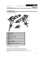
Page 16: ...Round spray nozzle H Atomizer air connection I Flat spray nozzle K Buttons to adjust the powder quantity L Gun body 5 2 FUNCTIONING OF THE SPRAY GUN High voltage is activated in the hand gun when the...

Page 17: ...MPa 43 51 psi Powder output quantity maximum of 450 g min 0 99 lbs min Ambient conditions Operating temperature range 5 45 C 41 113 F Relative humidity 75 5 3 TECHNICAL DATA Ambient conditions If low...

Page 18: ...PEM X1 A P_01662 B C OPERATING MANUAL VERSION 09 2012 ORDER NUMBER DOC 2326020 5 3 1 DIMENSIONS Measurement mm inch A 335 349 13 19 13 74 B 248 9 76 C 45 1 77 with flat spray nozzle with deflector co...

Page 19: ...conformity 1 2326019 Operating manual German 1 see chapter 1 5 Operating manual in the local language 5 5 SCOPE OF DELIVERY 5 4 PERMITTED ACCESSORIES Only the accessories listed in the chapter Access...

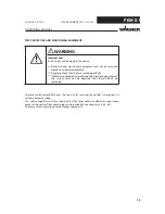
Page 20: ...ations for the additionally required system components WARNING 6 2 STORAGE CONDITIONS Until the point of installation the powder coating gun must be stored in a dry location free from vibrations and w...

Page 21: ...erview Powder cloud Flat spray nozzle Complex shapes Widely spread flat powder cloud Flat parts slight window frame effect Profiles Undercuts Deflector cone Round powder cloud Wire goods Size of the p...

Page 22: ...Large flat parts Output quantity g min Overall air Feed air 4 00 Nm h 5 00 Nm h 6 00 Nm h 50 140 170 210 60 200 240 260 70 250 270 300 80 300 320 350 90 330 360 380 100 370 400 420 The values have bee...

Page 23: ...the powder feed hose to the spray gun and to the powder injector 5 Connect the atomizing air hose to the spray gun and to the control unit 6 5 CONNECTING THE SPRAY GUN Unintentional putting into opera...

Page 24: ...NUAL VERSION 09 2012 ORDER NUMBER DOC 2326020 to the electrical connection on the control unit Powder feed from the powder injector Atomizing air from the control unit Powder spray gun Control unit Po...

Page 25: ...ystem is via the knurled screw on the rear of the control unit Both connections are absolutely essential If installed correctly as described above the gun is grounded via the gun cable between the con...

Page 26: ...or hooks hangers and work piece can occur if electric contact points between conveyor conveyor hooks hangers and work piece are not sufficiently cleaned and therefore the work pieces are not sufficien...

Page 27: ...iar with the provisions of European standards DIN EN 50050 2 and DIN EN 50177 WARNING Incorrect operation Risk of injury and damage to the equipment If contact with powder materials or cleaning agents...

Page 28: ...izing air should be adjusted for the flat spray nozzle to 0 1 Nm h round spray nozzle to 0 2 Nm h 2 Adjust the powder quantity and the powder speed on a test piece 7 3 OPTIMIZING THE POWDER CLOUD FOR...

Page 29: ...ORDER NUMBER DOC 2326020 7 4 SWITCHING OFF THE SPRAY GUN By releasing the trigger the powder supply is stopped and the high voltage switched off To safely switch off the spray gun e g for maintenance...

Page 30: ...o flashing By saving these settings the current values of the powder feed are taken over in the current recipe The blinking changes back to flashing By activating the double click function the blinkin...

Page 31: ...E HIGH DYNAMIC REMOTE This function is used to change quickly to another recipe during a coating operation The operator can access a previously set recipe by double clicking on the trigger lever on th...

Page 32: ...OC 2326020 7 7 REPRODUCIBLE SETTING OF THE NOZZLE POSITION An adjustment tool is provided for the flat spray nozzle This allows all flat spray nozzles to be turned without damaging the electrodes and...

Page 33: ...anual work the high voltage must be shut down and locked to prevent it from being switched back on The spray gun must be separated from the high voltage supply before any cleaning work is started Use...

Page 34: ...e adhered to for all cleaning work 8 1 3 CLEANING PROCEDURES Incorrect maintenance Risk of injury and damage to the equipment If contact with powder materials or cleaning agents causes skin irritation...

Page 35: ...INTENANCE STAFF 8 2 2 SAFETY INSTRUCTIONS Incorrect maintenance repair Risk of injury and damage to the equipment Have repairs and part replacements be carried out by specially trained staff or a WAGN...

Page 36: ...s x Check gun discharge pressure x Blow out powder hoses x Check grounding x Check compressed air quality x Check gun voltage x Check powder hoses for bends and sintering x 8 2 3 MAINTENANCE PROCEDURE...

Page 37: ...e spare parts list with must be regularly checked and if necessary replaced Procedure 1 Switch off control unit 2 Disconnect electrical cable 1 from control unit 2 3 Disconnect the hoses for powder fe...

Page 38: ...moved and from the spray gun Note Never place the spray gun or parts of the spray gun in cleaning agent As a rule the protective wedge needs to be checked for wear and replaced if necessary Procedure...

Page 39: ...turned by hand Procedure Note 1 Before inserting the electrode holder the spring contact of the gun body and contact surface of the electrode holder should be checked The spring contact must be clean...

Page 40: ...m remains inserted in the cap nut Note If the nozzle system doesn t remain inserted in the cap nut the nozzle system and cap nut must be replaced 4 Press nozzle system out of cap nut by gently pressin...

Page 41: ...n body and contact surface of the electrode holder should be checked The spring contact must be clean and smooth running the gun body must also be clean and free of powder deposits 2 Attach deflector...

Page 42: ...up to stop 3 Press manually without a tool the protective wedge 3 sideways out of wedge tool 1 Note A wedge tool is available to prevent the protective wedge from being damaged when dismantling and i...

Page 43: ...flush with the end Y of the electrode holder 3 The protective wedge is now correctly assembled and the wedge tool can be retracted out of the electrode holder 4 The protective wedge remains inserted i...

Page 44: ...UND SPRAY NOZZLE Procedure 1 Unscrew cap nut from the gun housing 2 Take cap nut with nozzle system off gun body The nozzle system remains inserted in the cap nut Note If the nozzle system doesn t rem...

Page 45: ...the gun body and contact surface of the electrode holder should be checked The spring contact must be clean and smooth running the gun body must also be clean and free of powder deposits 6 Insert elec...

Page 46: ...peel Procedure 1 Guide plug in contact 1 of Corona Star into hole B on hook 2 Attach clip 2 of Corona Star to housing Flexible positioning in a range of 90 is possible Danger from electric current Ris...

Page 47: ...6020 8 10 REPLACING THE SUSPENSION HOOK Procedure 1 Loosen retaining bolts on rear of hook and unscrew 2 Slide hook in direction indicated by arrow and remove from gun housing 3 Fit new hook on receiv...

Page 48: ...R NUMBER DOC 2326020 9 INSPECTIONS IN ACCORDANCE WITH DIN EN 50177 2010 If the system is used for electrostatic coating with flammable coating powders testing should be undertaken in accordance with D...

Page 49: ...stopped and the material supply supply air and high voltage are switched off when the ventilation is shut down Annually 3 Eff ectiveness of grounding measures All the system s conductive elements such...

Page 50: ...sistance to ground of work piece s locating point The resistance to ground of every work piece s locating point must not exceed 1 megaohm measurement voltage must be 1000 V The design of the work piec...

Page 51: ...The discharge equipment must be interlocked with the spray system such that the high voltage is switched off and that coating cannot take place if the discharge equipment malfunctions BP ME FU S Meas...

Page 52: ...t one of our service points one of our representatives or us directly to this purpose NOTICE 10 2 DISPOSAL 10DISASSEMBLY AND DISPOSAL 10 1 DISASSEMBLY Procedure 1 Switch off the system 2 Lock the supp...

Page 53: ...spray gun and device pressure Secure the spray gun against actuation Observe the operating and service instructions when carrying out all work DANGER Incorrect maintenance repair Danger to life and e...

Page 54: ...er outlet uneven or inadequate Contamination Blow through parts carrying powder Powder sintering Clean parts carrying powder Feed device contaminated See operating instructions for the related devices...

Page 55: ...FLAT SPRAY NOZZLE Order No Designation 2321976 X1 flat spray nozzle complete 12 2 DEFLECTOR CONE Order No Designation 2321981 D18 deflector cone complete 2321980 D25 deflector cone complete 2321171 D3...

Page 56: ...up complete 2322768 D8 D10 hose take up complete 12 5 RETROFIT SET CORONA STAR Pos Order No Designation 2322868 PEM X1 Corona Star complete 1 2322835 PEM X1 Corona Star electrode complete P_01696 12 6...

Page 57: ...351794 Powder hose 9 mm 2310699 Powder hose 10 mm 2307502 Powder hose 11 mm 2310700 Powder hose 12 mm Pos K Stk Order No Designation 1 2323366 X1 VL 150 nozzle extension 150 mm 5 91 inches 1 2323356 X...

Page 58: ...58 PEM X1 OPERATING MANUAL VERSION 09 2012 ORDER NUMBER DOC 2326020 P_01861 12 9 WALL MOUNT Order No Designation 2330223 Wall mount with bracket...

Page 59: ...ion 2325320 X1 powder measuring adapter with bag complete for measuring powder quantities for the PEM X1 spray gun The powder measuring adapter is slid onto the nozzle Risk of explosion due to electro...

Page 60: ...re parts lists Address for invoice Address for delivery Name of the person to be contacted in the event of any queries Type of delivery normal mail express delivery or courier etc Wearing parts Note N...

Page 61: ...rona manual spray gun 2 1 2322761 Hose take up D10 12 complete 3 2 9971364 O ring 4 1 2320464 Cap nut X1 5 1 2321976 Flat spray nozzle X1 complete 6 1 2322529 Electrode holder X1 F ET 7 1 2320488 Repl...

Page 62: ...R with nozzle 2 1 2322490 Electrode holder X1 R ET 3 1 2320488 Replacement protective wedge X1 4 1 2320503 Deflector cone sleeve X1 5 1 2321981 D18 deflector cone complete 6 1 2321980 D25 deflector co...

Page 63: ...rial costs will be borne by us except where these costs are increased due to the subsequent shipment of the unit to a location other than the address of the purchaser We do not provide warranty for da...

Page 64: ...DIN EN 50050 2007 DIN EN 1127 1 2008 DIN EN 60079 0 2010 DIN EN 60079 31 2010 DIN EN 60079 7 2007 DIN EN 1953 2010 DIN EN 60204 1 2007 DIN EN 13890 2009 DIN EN 14462 2010 DIN EN 60529 2000 DIN EN ISO...

Page 65: ...65 PEM X1 OPERATING MANUAL VERSION 09 2012 ORDER NUMBER DOC 2326020 14 4 EC TYPE EXAMINATION CERTIFICATE...

Page 66: ...66 PEM X1 OPERATING MANUAL VERSION 09 2012 ORDER NUMBER DOC 2326020...

Page 67: ...67 PEM X1 OPERATING MANUAL VERSION 09 2012 ORDER NUMBER DOC 2326020...

Page 68: ...68 PEM X1 OPERATING MANUAL VERSION 09 2012 ORDER NUMBER DOC 2326020 14 5 FM APPROVAL in submission...

Page 69: ...69 PEM X1 OPERATING MANUAL VERSION 09 2012 ORDER NUMBER DOC 2326020...

Page 70: ...ce fr Netherlands WAGNER Systemen Nederland Proostwetering 105 C NL 3543 AC Utrecht Phone 31 30 2410 688 Fax 31 30 2410 765 E mail info wagnersystemen nl Italy WAGNER Itep S p A Via Santa Veccia 109 I...

Page 71: ......

Page 72: ...stfach 1120 D 88677 Markdorf Tel 49 0 7544 5050 Fax 49 0 7544 505200 E mail service standard wagner group com Switzerland J WAGNER AG Industriestrasse 22 Postfach 663 CH 9450 Altst tten Tel 41 0 71 75...

Reviews: