

M001XLLP
WARNING
!
!
USE OF TIPOVER RESTRAINTS MAY ONLY REDUCE, BUT NOT ELIMINATE RISK OF TIP OVER.
SMALL PARTS- NOT FOR CHILDREN UNDER 3 YEARS. ADULT SUPERVISION IS REQUIRED.
If you do not understand these directions, or if you have any doubts about the safety of the installation, please call a
qualified technician. Check carefully to make sure there are no missing or defective parts. Improper installation may
cause damage or serious injury. Do not use this product for any purpose that is not explicitly specified in this manual.
Do not exceed weight capacity. We cannot be liable for damage or injury caused by improper mounting, incorrect
assembly or inappropriate use.
SERIOUS OR FATAL CRUSHING INJURIES CAN OCCUR FROM TIPOVER. TO HELP PREVENT TIPOVER:
Dual Mount with Laptop Tray
75x75\100x100
INSTALLATION MANUAL
1-844-SATTLER (18447288537)
support@walielectric.com
www.walielectric.com
(10kg/22lbs)x2
RATED
TIPOVER WARNING
● NEVER ALLOW CHILDREN TO CLIMB, STAND, HANG, OR PLAY ON ANY PA
RT OF MONITOR OR STAND.
● USE TIPOVER RESTRAINT OR ANCHOR STAND TO WALL.
Supplied Parts List
Lower Pole
a1 (x1)
Upper Pole
a2 (x1)
C-Clamp Brace
c (x1)
C-Clamp
b (x1)
VESA Plate
e (x2)
M8x12 Bolt
g (x2)
Nut
h (x2)
M5x14 Bolt
f (x3)
Support Plate
j (x1)
Spring Washer
l (x1)
M10 Washer
k (x1)
M10 Bolt
i (x1)
Grommet Base Plate
m (x1)
Wire Clip
n1 (x2)
Allen Key
o (x1)
Wire Clip
n2 (x3)
M4 Spacer
s (x8)
M4x30 Bolt
r (x8)
Wrench
p (x1)
M4x12 Bolt
q (x8)
Swivel Arms
d (x1)
Laptop Tray
t (x1)
M4 Nut
v (x4)
M4x10 Bolt
u (x4)
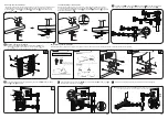
Option A : Clamp Installation
1. Connect Pole a and C-Clamp Brace c from the bottom using M5x14 Bolt f and
tighten with Allen Key 3mm o .
2
2. Select the preferred height according to your desk thickness. Connect C-Clamp b to C-Clamp
Brace c using M8x12 Bolt g and tighten with Allen Key 5mm o . Rotate the hand knob
clockwise to fasten for stability.
Hand Knob
a
c
c
c
f
o
o
o
g
g
b
b
a
c
f
o
Option B : Grommet Base Installation
1. Place Pole a onto Grommet Base Plate m . Connect them from the bottom using
M5x14 Bolt and tighten with Allen Key 3mm .
o
o
a
a
m
m
f
f
Laptop : 17” Max
Monitor: 32” Max
Anti-skid Pad
w (x4)
1
a2
a2
a1
a1
a1
o
o
31.5'' Pole Installation
Loosen the screw on the Lower Pole
a1
with Allen key 2mm o . Connect
Lower Pole
a1
to Upper Pole
a2
and tighten the screw with Allen key
2mm o to fix the two poles.
a1
a1
Pre-Assembly
o
a2
o


