background image

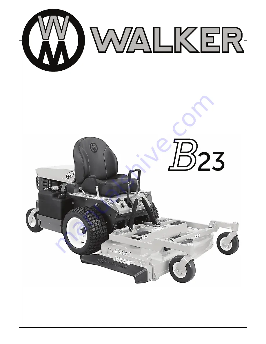
Operator’s Manual

Safety, Assembly, Operating, and Maintenance Instructions

Please Read and Save These Instructions

For Safety, Read All Safety and Operation 
Instructions Prior to Operating Machine

Beginning S/N: 178742

P/N 4000-44

Summary of Contents for B23

Page 1: ...nual Safety Assembly Operating and Maintenance Instructions Please Read and Save These Instructions For Safety Read All Safety and Operation Instructions Prior to Operating Machine Beginning S N 17874...

Page 2: ...ry to the operator or others If anything in this manual is confusing or hard to understand please contact your local authorized dealer or call our service department at 970 221 5614 for clarification...

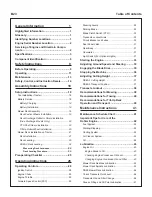
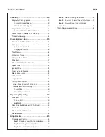
Page 3: ...Engine Choke 29 Engine Throttle 29 Forward Speed Control FSC 29 Steering Levers 29 Parking Brake 29 Blade Clutch Switch PTO 30 Transaxle Lockout Arms 30 Circuit Breaker and Fuses 30 Seat Panel Latch...

Page 4: ...el Lines and Clamps 58 Blade Brake Action 58 PTO U Joints 58 Engine Starter 58 Safety Switch System 58 Forward Speed Control Friction Lock 59 Transmission Control Setting 59 Neutral Park 59 Straight G...

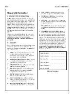
Page 5: ...actor when the operator is seated facing forward in the tractor seat POWER TAKE OFF PTO transmits engine power to run the cutter blades RIGHT HAND RH refers to the right hand side of the tractor when...

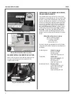
Page 6: ...important to find a local authorized servicing agent of the component manufacturer Any unauthorized work done on these compo nents during the warranty period may void the warranty If you have any dif...

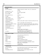
Page 7: ...200 Hour Kohler Filter P N 12 050 01 S Cooling System Air Cooled Fuel Tank Capacity gal L 4 7 17 8 Fuel Regular Grade Unleaded Gasoline 87 Octane Minimum 10 Ethanol Maximum Air Cleaner Remote Mounted...

Page 8: ...Shaft with Two 2 High Speed U Joints Blade Drive Clutch and Brake Ogura Electric Clutch with Soft Start Engagement and Mechanical Brake Stops Blades within Five 5 Seconds of Disengagement TIRE SIZE D...

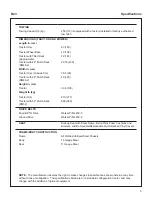
Page 9: ...lb kg Tractor Only 610 277 Tractor with 52 Mulch Deck DM52 848 385 DRIVE BELTS Engine PTO Drive Walker P N 4230 3 Ground Drive Walker P N 4230 2 SEAT Built up Seat with Steel Frame Extra Thick Foam C...

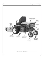
Page 10: ...Right Side View Deck Caster Wheels Tilt Up Latch Seat Panel Latch Counterweight Springs and Protective Covers Deck Support Pins and Height Adjustment Hitch Pins Deck Support Arm Forward Speed Control...

Page 11: ...r View and Left Side View Left Hand Drive Wheel Cylinder Head Cooling Fins Spread Axle Tail Wheel Footrests Tailpipe Muffler Guard Muffler Heat Shield Rear Body Shown or Optional Dump Bed Tailwheel Fo...

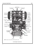
Page 12: ...t Arm 30 Amp Master Circuit Breaker Not Visible Donaldson Air Cleaner Dipstick Parking Brake Linkage Turbine Precleaner Battery Box and Cover Air Filter Restriction Gauge Electric PTO Clutch Transaxle...

Page 13: ...d by Walker Manufacturing must take full responsibility for safety The Walker Rider Lawnmower has been designed with many safety features to protect the operator from personal harm or injury However i...

Page 14: ...U TRAL PARK 2 PTO Clutch ENGAGED or 3 Parking Brake DISENGAGED NOTE There is a 1 2 second time delay function on the seat switch to avoid engine power interruption when driving over bumps 10 Handle ga...

Page 15: ...nterlock switch normally prevents starting of the machine if these controls are in the OPERATING position 7 Do not operate machine if the operator presence safety switch system is not work ing Verify...

Page 16: ...c Disconnect the spark plug wires d Never place hands under the deck use a stick or similar tool to remove clogged material 19 If the cutting blades strike a solid object or the machine begins to vib...

Page 17: ...n any man ner which adversely affects its operation perfor mance durability or use will VOID the warranty and may cause hazardous condi tions 8 Never attempt to disconnect any safety devic es or defea...

Page 18: ...nd ear protection when operating the machine 3 Warning crushing dismemberment hazard of bystanders Do not carry passengers Always stop the machine if someone enters the area 4 Warning thrown object ha...

Page 19: ...e speed Move lever back to stop 2 Warning read Operator s Manual before servicing or performing maintenance Engage parking brake Remove ignition key 3 Warning do not operate the machine without a deck...

Page 20: ...ds and feet Keep all body parts away from rotating mower blades Do not step on end of deck 8600 14 Location Deck Carrier Frame Part Number 8600 14 Warning do not operate the machine with the deck tilt...

Page 21: ...k cutting height 8600 9 60 lb ft 81 N m Location Gearbox Cover Gear Driven Decks Only Part Number 8600 9 Tighten blade nuts on gear driven decks to 60 lb ft 81 N m 8600 12 Location Underside of Rear B...

Page 22: ...ase resulting in acid leakage and severe damage to the machine A hazard may be created by damage to critical working parts and safety systems CAUTION Important Battery Service Installation and Chargin...

Page 23: ...tery Clamp Secured by Wing Nut s Battery Installation Battery Cover Two 2 10 24 Threaded Knobs Mount Cover Battery Cover Installation Mower Deck Assembly CAUTION The engine must be off during the trac...

Page 24: ...ed and in the lowest possible position Attach Shield Deck Discharge Shield Installation PTO Shaft Guard Installation Position the shaft guard as shown and mount with two 2 1 4 20 x 1 2 in bolts Attach...

Page 25: ...TO coupler tube onto the tractor s PTO drive shaft Make sure the ring has snapped securely on the spline shaft IMPORTANT To prevent damage to the mow er make sure the PTO quick disconnect is securely...

Page 26: ...or remove the block CAUTION Do not operate the machine with the deck tilt up pivot joint unlocked Deck Lock Lever Engaged Deck Lock Levers Engaged 10 Raise the seat panel to the open position Then rai...

Page 27: ...dure 2 Check the side to side level Rotate each blade sideways and measure the distance from blade tip to ground on each side If mea surements vary more than 1 8 in 3 mm add a washer shim under the de...

Page 28: ...o side and front to back deck level mea surement points Side to side measurements should not vary more than 1 8 in 3 mm Front to rear measurements should have the rear 1 4 in 6 mm to 3 8 in 10 mm high...

Page 29: ...operating the mower for the first time and as a routine before daily operations it is important to make sure the mower is properly prepared and ready for operation The following is a list of items to...

Page 30: ...C TRANSAXLE OIL LEVEL Refer to Check Transaxle Fluid Level on page 46 for details F CHECK FUNCTION OF SAFETY INTERLOCK SWITCHES Refer to Safety Switch System on page 58 to check for proper operation o...

Page 31: ...n the tilt up position F CHECK MOWER BLADE CONDITION SHARPNESS AND SECURITY OF MOUNT ING The blade mounting nuts on gear driven decks should be torqued to 60 lb ft 81 N m and the blade mounting bolts...

Page 32: ...tion Ignition Switch When starting the engine turn the key clockwise to the START position Do not hold the key in this position longer than 10 seconds If the engine does not start return the key to th...

Page 33: ...C setting and slows or stops forward travel Releasing the steering levers allows the tractor to resume forward travel at the speed set by the FSC lever To stop and park the machine the FSC lever is mo...

Page 34: ...recessing them back toward the chassis the transaxles are engaged for normal operation The transaxle arms in the LOCKOUT position are used to enable moving the machine without the engine running e g...

Page 35: ...optional dump bed is hinged and tilts back for maintenance access Lifting Rear Body Hourmeter The hourmeter which is located on the left front of the seat panel displays operating time accumu lated wh...

Page 36: ...rd Position No Control Change Full Forward Ground Speed Position Neutral Park Position BLADE CLUTCH PTO Neutral Park Position Intermediate Ground Speed Position Fast Throttle Position Idle Position Th...

Page 37: ...cool down period between starting attempts Failure to follow these guidelines can damage the starter motor and shorten battery life Consult your Walker dealer or authorized Kohler dealer for addi tio...

Page 38: ...in reverse by rapidly pulling on the steering levers especially when go ing downhill as this can lift the tractor tail wheel off the ground and set up a bucking motion due to operator overcontrol If...

Page 39: ...rolling the inside wheel into re verse for a smooth rolling turn one wheel roll ing forward while the other rolls backward Practice maneuvering the mower un til you can make it go exactly where you ar...

Page 40: ...NOT disengage the blade clutch with high engine speed above 1 2 throt tle since excessive brake action on the blade drive will cause premature wear of the brake WARNING A brake stops the cutter blades...

Page 41: ...adjusting cutting height or servicing move the Forward Speed Control FSC into the NEUTRAL PARK position engage the parking brake and disengage the blade clutch PTO Tractor should not be moving while...

Page 42: ...e mower will freewheel with the arms in the LOCKOUT position The levers must be in the highest position to completely unlock the transaxles Transaxle Lockout Arm Transaxle Lockout Arm Freewheel Positi...

Page 43: ...ppearance and vary the direction of the stripe each time the grass is mowed to avoid wear patterns in the grass Avoid damage to the grass by slipping and skid ding of the drive tires Use smooth contro...

Page 44: ...ls on the back of the deck may be damaged by moving the tractor The tilt up configuration should only be used when the tractor is parked The tractor seat should never be tilted forward with the deck i...

Page 45: ...Fuel Filter x 63 Change Transaxle Oil and Filter x 46 Replace Air Filter Element and Safety Filter x 52 Check Adjust FSC Friction Lock x 59 Check Fuel Lines and Clamps x 58 Service Engine Starter x 5...

Page 46: ...full horse power and move more cooling air through the engine cool ing fins Air Cleaner System Use only Donaldson air cleaner elements Aftermarket elements may not seal in the air cleaner housing allo...

Page 47: ...vel surface with the en gine stopped Also make sure the engine is cool and oil has had time to drain into the sump allow at least five 5 minutes after stopping the engine IMPORTANT NEVER check or add...

Page 48: ...gasket on the replacement oil filter IMPORTANT Use ONLY Kohler oil filters See the Specifications section for a list of recommended filters After market oil filters may not seal properly and or may n...

Page 49: ...relubricate the gearbox assembly as follows 1 Remove gearbox cover footrest Deck orien tation should be the normal operating position Tee Gearbox Blade Drive Gearboxes Mower Deck Gearboxes Shown with...

Page 50: ...olly Wheel and U Joint Lubrication Check Transaxle Fluid Level The transaxle oil lubrication is SAE 20W 50 API Service Class SL or higher engine oil Inspect both transaxle cases and hoses after every...

Page 51: ...se there may be air trapped in the transaxle that needs to be purged To purge air from transaxle raise the tractor and block with tires off the ground With engine running slowly move the Forward Speed...

Page 52: ...e Idler Pivot Grease 1 21 Transaxle Oil Reservoir Oil 20W 50 1 Ident Lubrication No No Location Type Places 22 Engine Oil Fill Oil 1 23 Tail Wheel Caster Fork Pivot Grease 2 24 RearAxle Pivot Grease 1...

Page 53: ...Maintenance Instructions Lubrication 49 Chassis and Deck Lubrication Points DM48 Shown 1 1 2 2 11 12 7 4 4 5 13 4 5 4 12 16 17 21 23 18 19 15 24 23 26 25 28 30 29 28 15 19 27 14 20 9804 1 9804 1 22 25...

Page 54: ...ing Cylinder Head Cooling Fins It is essential for performance and longevity of the air cooled engine to keep the cylinder head cooling fins clean and free of obstruction After every 8 hours of operat...

Page 55: ...ealing action reducing the possibility of dust leaks due to improper filter installation Intake design internal baffling and a dust ejection valve provide dust separation and automatic precleaning act...

Page 56: ...filter element if excessive air flow restriction has been indicated by the air filter restriction gauge and proceed to Step 6 Clean the filter element by gently tapping on a flat hard surface If exces...

Page 57: ...eplacement 10 Install the cover with the word TOP properly oriented to the top of the canister Give the cover a slight twist as it reaches the canister to make sure the tab inside the cover goes into...

Page 58: ...Do not operate machine with deck tilt up pivot joint unlocked Transaxle Housing Keeping the housing of the transaxles clean and free of obstruction is essential to avoid overheat ing the transaxle fl...

Page 59: ...ttery The battery comes sealed and is maintenance free so the electrolyte level will not need to be checked or filled IMPORTANT Make sure battery is securely mount ed in the frame A loose battery may...

Page 60: ...type grass or operating on sandy soils Replace blades if worn bent cracked or otherwise damaged refer to Mower Blades on page 64 Use the following proce dure to check and sharpen blades NOTE Keep bla...

Page 61: ...anced on Magnetic Wall Mounted Balancer 7 Mount the blade with wing tips pointing up into the housing For gear driven decks reinstall the blade washer lock washer and nut Tighten the nut to 60 lb ft 8...

Page 62: ...nds the electric clutch brake assembly will need to be repaired or replaced Contact your Walker Dealer for this service PTO U Joints The PTO U joints should be inspected yearly for looseness and wear...

Page 63: ...e FSC friction lock needs to be adjusted refer to Adjustments for Transmission Control Step 6 Forward Speed Control Friction Adjustment on page 67 Transmission Control Setting On a yearly interval or...

Page 64: ...ve Belts There are two 2 individual belts on the machine Engine PTO Drive Belt Ground Drive Belt The belts may be removed and replaced using the following procedures Remove Belts 1 Lift up on the belt...

Page 65: ...cing and Repairing Engine PTO Drive Belt Ground Drive Belt LH Transaxle Drive Pulley Belt Tightener Idler Pulley RH Transaxle Ground Drive Belt Engine PTO Belt PTO Belt Tightener Idler Pulley Fixed Id...

Page 66: ...g Rotate Clevis and Belt Tensioner Stop Bolt Rotate Belt Tensioner Arm Remove Belt Tension 2 To install the deck drive belt a Install and route the belt as shown on the belt routing decal located on t...

Page 67: ...5020 3 or Kohler P N 24 050 13 9 12 microns for replacement filter In Line Fuel Filter Fuel Filter Location Fuel Pump Fuel Pump Location IMPORTANT Replace the fuel filter only in a clean area where t...

Page 68: ...he blade turns up to form the wing tip refer to the illustration Mower Blade Profile for Sharpening on page 57 for location of the wing tip and wear area Since sand and abra sive material can wear met...

Page 69: ...ne an other If they are not equal adjust accord ingly The handles may or may not be even at this point NOTE The LH steering lever is non adjust able This procedure will require adjustment of the RH le...

Page 70: ...lockwise just until the wheel stops and then begins to move in reverse Rotate the control rod back coun terclockwise half the number of turns required to make the wheel go from moving forward to rever...

Page 71: ...ing the levers to alignment Tighten the jam nut 3 Test drive the machine to confirm that straight tracking is being achieved at maximum for ward speed FSC lever in full forward posi tion T Handle Hex...

Page 72: ...adjust ment should sit flush on the washers above the deck pin bushing On a level surface if any pin is sticking up likely the front pins tighten the oppo site side or loosen the same side to lower th...

Page 73: ..._______________________________________________________________________________ ______________________________________________________________________________________________________________ _________...

Page 74: ..._______________________________________________________________________________ ______________________________________________________________________________________________________________ _________...

Page 75: ...product alterations or failure to follow the instructions contained in the Operator s Manual for operation and maintenance B The customer shall pay any charges for making service calls and or for tran...

Page 76: ...WALKERMFG CO 5925E HARMONYROAD FORTCOLLINS CO80528 970 221 5614 FORM NO 071123 PRINTED IN USA www walker com 2023 WALKER MFG CO...

Reviews: