
©2018 Warn Industries, Inc. WARN® and the WARN logo are trademarks of Warn Industries Inc.
1
101799A0
WARN INDUSTRIES, INC.
12900 S.E. Capps Road,
Clackamas, OR USA 97015-8903, 1-503-722-1200, FAX: 1-503-722-3000
Customer Service:
1-800-543-9276
Dealer Locator Service:
1-800-910-1122
International Fax:
1-503-722-3005
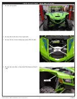
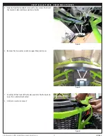
INSTALLATION INSTRUCTIONS
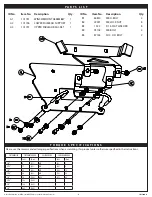
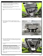
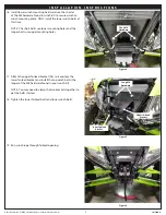
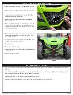
Winch Mount
Part Number: 101672
Application:
2018 Arctic Cat Wild Cat
G E N E R A L S A F E T Y P R E C A U T I O N S
W A R N I N G
IMPACT AND MOVING PARTS ENTANGLEMENT HAZARD
Failure to observe these instructions could lead to severe injury or death
• Always
take time to fully read the Instructions and/or Operations Guide, and/or Basic Guide to Winching Techniques, in order to understand your winch and its operations.
• Always
use extreme caution when drilling on any vehicle. Make sure that all fuel lines, brake lines, electrical wires, and other objects are not punctured or damaged when/if drilling on the
vehicle. Thoroughly inspect the area to be drilled (on both sides of material) prior to drilling, and relocate any objects that may be damaged. Failure to inspect the area to be drilled may result in
vehicle damage, electrical shock, fire or personal injury.
• Always
wear safety glasses when installing this kit. A drilling operation will cause flying metal chips. Flying chips can cause eye injury.
• Always
use extreme caution when cutting and trimming during fitting.
• Always
remove jewelry and wear eye protection.
• Never
lean over battery while making connections.
• Never
route electrical cables:
o Across any sharp edges.
o Through or near moving parts.
o Near parts that become hot.
• Always
insulate and protect all exposed wiring and electrical terminals.
• Always
install terminal boots as directed in installation instructions.
• Always
use appropriate and adequate care in lifting components into place.
• Always
insure components will remain secure during installation and operation.
• Always
tighten all nuts and bolts securely, per the installation instructions.
• Always
perform regular inspections and maintenance on the plow mechanism, fasteners, cable and related hardware.
• Always
replace all worn or damaged parts before operating.
• Never
operate this WARN product with damaged or missing parts.
Read installation and operating instructions thoroughly.
Your safety, and the safety of others, is very important. To help you make informed decisions about safety, we have
provided installation and operating instructions and other information on labels and in this guide. This information
alerts you to potential hazards that could hurt you or others. It is not possible to warn you about all potential hazards
associated with this product, you must use your own good judgment.
CARELESS INSTALLATION AND OPERATION CAN RESULT IN SERIOUS INJURY OR EQUIPMENT DAMAGE. READ AND
UNDERSTAND ALL SAFETY PRECAUTIONS AND OPERATING INSTRUCTIONS BEFORE INSTALLING AND OPERATING
THIS PRODUCT.
This guide identifies potential hazards and has important safety messages that help you and others avoid personal injury
or death. WARNING and CAUTION are signal words that identify the level of hazard. These signal words mean:
WARNING signals a hazard that could cause serious injury or death, if you do not follow recommendations. CAUTION
signals a hazard that may cause minor to moderate injury, if you do not follow recommendations.
This guide uses NOTICE to call attention to important mechanical information, and Note: to emphasize general information
worthy of special attention.


