


Installation
Guide
P/N 96P557A01 rev. 2/99
Geothermal System Single-Speed
Installation and Maintenance Manual
208-230/60/1 & 208-230/60/3
WARNING: Before performing service or maintenance operations on a system,
turn off main power switches to the indoor unit. If applicable, turn off the accessory heater
power switch. Electrical shock could cause personal injury.
Installing and servicing heating and air conditioning equipment can be hazardous due to
system pressure and electrical components. Only trained and qualified service personnel should
install, repair or service heating and air conditioning equipment.
Untrained personnel can perform the basic maintenance functions of cleaning coils and
cleaning and replacing filters. All other operations should be performed by trained service
personnel. When working on heating and air conditioning equipment, observe precautions in the
literature, tags and labels attached to the unit and other safety precautions that may apply.
Follow all safety codes. Wear safety glasses and work gloves. Use a quenching cloth for
brazing operations and have a fire extinguisher available.
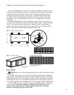
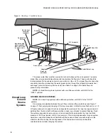
Move units in the normal “up” orientation as indicated by the arrows on each carton. Horizon-
tal units may be moved and stored per the information on the carton. Do not stack more than
three units in total height. Vertical units may be stored one upon another to a maximum height of
two units. Do not attempt to move units while stacked. When the equipment is received, all items
should be carefully checked against the bill of lading to be sure all crates and cartons have been
received. Examine units for shipping damage, removing the units from the cartons if necessary.
Units in question should also be internally inspected. If any damage is noted, the carrier should
make the proper notation on the delivery receipt, acknowledging the damage.
Moving and
Storage
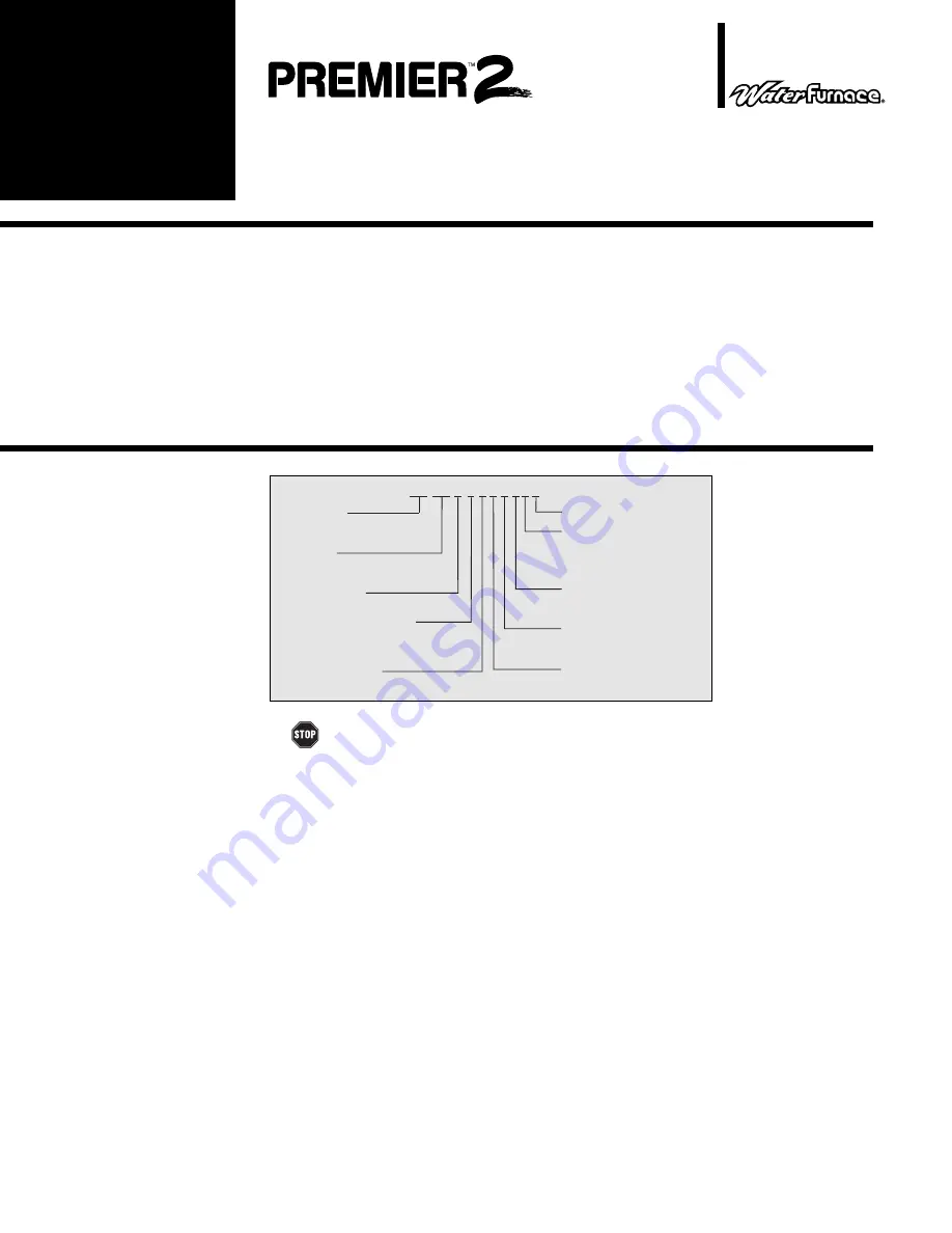
Model
Nomenclature
Table of
Contents
Model Nomenclature 1
Safety Considerations 1
Moving and Storage 1
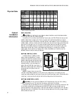
Physical Data 2
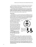
General Installation Information 2-5
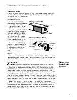
Closed Loop Cooler/Boiler Systems 5-6
Closed Loop Ground Source Systems 6-8
Open Loop Groundwater Systems 8-9
Desuperheater Connection
9-10
Initial Desuperheater Start Up 10-11
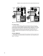
Electrical Connections 11-12
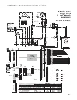
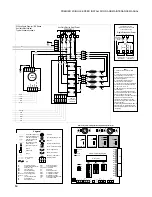
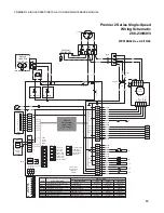
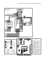
Wiring Schematics 13-16
Thermostats 17
Microprocessor Control Operation 17-19
Blower Speed 19
Blower Performance 20
Unit Start-Up 20-22
Preventive Maintenance 23
Troubleshooting 24
Replacement Procedures 24
Unit Operating Pressures 25
Unit Electrical Data 25
Safety
Considerations
Model Type
ATV= Vertical Premier Unit
ATH= Horizontal Premier Unit
Non-Standard Options
Coax Options
C = Copper
N = Cupronickel
Unit Size
034 = 34,000 BTUH Nominal cooling at
90
°
F entering water
Design Vintage
C or higher = Premier2
Return Air Options
L = Left return
R = Right return
For Future Use
ATV
D
034
1 1 0 C L T X
Electrical Characteristics
0 = 208-230/60/1 Commercial
1 = 208-230/60/1 Residential
3 = 208-230/60/3 Commercial
Discharge Air Options
B = Bottom discharge (Vertical)
T = Top discharge (Vertical)
T = End discharge (Horizontal)
T = Side discharge (Horizontal)
Hot Water Options
0 = No hot water option
1 = Hot Water Generation w/pump
Summary of Contents for AT019D
Page 20: ......
Page 21: ......
Page 26: ...26 PREMIER 2 SINGLE SPEED INSTALLATION AND MAINTENANCE MANUAL Notes...
Page 27: ...27 PREMIER 2 SINGLE SPEED INSTALLATION AND MAINTENANCE MANUAL...


