background image


12.11.2015 

1 / 60 

Z21826 

Copyright 

 2013 by: WATERKOTTE GmbH. Subject to changes 


Planning and installation 

Basic Line Ai1 Geo 

Heating station 


WATERKOTTE GmbH, Gewerkenstraße 15, D-44628 Herne 

Tel.: +49 2323 9376 0, Fax: +49 2323 9376 99 

Service: +49 2323 9376 350 

E-Mail: info@waterkotte.de Internet: http://www.waterkotte.de 

Summary of Contents for EcoTouch Ai1 Geo

Page 1: ...mbH Subject to changes Planning and installation Basic Line Ai1 Geo Heating station WATERKOTTE GmbH Gewerkenstra e 15 D 44628 Herne Tel 49 2323 9376 0 Fax 49 2323 9376 99 Service 49 2323 9376 350 E Ma...

Page 2: ...ritten approval by WATERKOTTE GmbH Illustrations and diagrams serve as explanatory description and shall not be used as drawings for construction offers or installation All specifications comply with...

Page 3: ...Line Ai1 Geo 13 4 2 Structure 13 4 2 1 Heat pump module 13 4 2 2 Compressor 13 4 3 Electrical equipment 14 4 3 1 Electrical resistance heating 14 4 3 2 Domestic hot water heating system 14 4 3 3 Heat...

Page 4: ...llel operation Heat pump and electrical heat generator 36 9 3 Heat generator thermostat settings 36 9 4 Installation instructions for an external sensor 36 9 4 1 Instalation of the cabling 37 9 5 Elec...

Page 5: ...ve 2002 96 EG Article 10 The product has been designed and manufactured with high quality materials and components which are suitable for recycling This symbol means that electrical and electronic equ...

Page 6: ...formed by trained specialist staff Damages resulting from failure to observe the points above are not in the scope of the warranty see attached warranty exclusion 1 2Basic safety precautions 1 2 1 Kee...

Page 7: ...are subject to written approval by WATERKOTTE Use only original spare parts from WATERKOTTE Original spare parts are specially designed for your heat pump Externally pro cured parts provide no guarant...

Page 8: ...her ignition sources Risk of total loss The heat pump is not a toy Keep children away from the heat pump in particular from the operating input device touch screen Read the accompanying technical manu...

Page 9: ...bserved Thus your heat pump is state of the art and provides for maximum safety In practice however this safety can only be ensured by taking all necessary measures As operator of the heat pump it is...

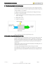
Page 10: ...tank Figure 1 Energy share while using a geothermal energy pump 2 1Description of operation Basic Line Ai1 Geo The WATERKOTTE heating central Basic Line Ai1 Geo uses a heat pump as heat generator At t...

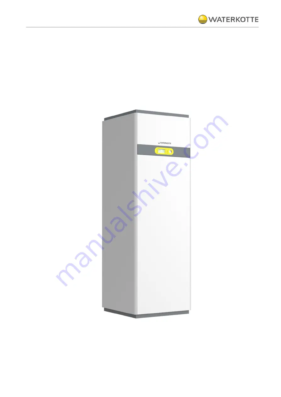
Page 11: ...Product description 12 11 2015 11 60 Z21826 Copyright 2013 by WATERKOTTE GmbH Subject to changes 3 Product description 3 1Overview Figure 2 Basic Line Ai1 Geo closed 1 Display 2 ON OFF switch...

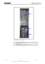
Page 12: ...ct description 12 11 2015 12 60 Z21826 Copyright 2013 by WATERKOTTE GmbH Subject to changes Figure 3 Basic Line Ai1 Geo open 1 Tank for domestic hot water 2 Control board 3 Connecting terminal 400 V s...

Page 13: ...l with BASICPRO Mobile Software diagnostic system All hydraulic connections positioned on the back All units within the scope Vice mounted with removable all round heat and sound insulated lining colo...

Page 14: ...e Consisting of heat source circulator speed controlled energy efficiency class A connections for ahead and return facilitates installation in the rear wall frame out wards 4 3 4 Electronic heat pump...

Page 15: ...igital soft starter for retrofitting at 3 x 400 V compres sor design basement pad 4 4Hydraulical equipment 4 4 1 Domestic water heating technology Stainless steel plate heat exchanger made in high vac...

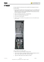
Page 16: ...and transporting the unit to prevent hand inju ries from cooling fins or other parts Observe the transport information on the packaging Observe the specified storage requirements The units may not be...

Page 17: ...uring transport it must be ensured that appro priate means of transport are used lift truck transport rollers handcart Unit must be transported upright Transport in tilted position 45 is permitted onl...

Page 18: ...mmended Acoustics in installation rooms with rigid walls can noticeably increase operating noise Counter measure acoustic insulation of one of the opposite wall or ceiling surfac es 6 2Creating the fo...

Page 19: ...ges 6 2 1 Heat pump base 1 Heat pump 2 Insulation strip polyethylen PE 3 Insulation material 3 layer polyurethan rubber 4 Supporting subsurface 5 Insulation material 6 Screed 7 Concrete plinth Dimensi...

Page 20: ...p and tank 7 1Accessories scope of delivery Piece Item No Description 1 Z21241 Installation manual Basic Line Ai1 Geo 1 Z21327 User manual Control 1 Z15312 Installation document Acceptance and Install...

Page 21: ...ubject to changes 7 2Installation The heat pump gets delivered completely installed Transport the heat pump module to the intended site Align the heat pump module in a horizontal position To do this u...

Page 22: ...hydraulical circuit and void the drinking water storage Free the connecting hose to the storage up and low see the pictures Figure 6 Storage connectings left storage connecting top with vent valve Sep...

Page 23: ...h the heat pump Use this tool to remove the panels and avoid damage Procedure Keep distance between the dismantling tools and the sheet edge to keep the retaining pin undamaged see figure The dismantl...

Page 24: ...ction rear Pos Description Thread A Connections for compressors heating element sensor etc 1 Hot water OUT G i 2 Cold water IN G i 3 Heat source IN heat pump entry G 1 a flat sealing seal Z14872 4 Hea...

Page 25: ...Installation und connection 12 11 2015 25 60 Z21826 Copyright 2013 by WATERKOTTE GmbH Subject to changes 8 2Connecting dimensions Figure 8 All connections in mm Basic Line Ai1 Geo rear...

Page 26: ...cting unions screwed on with suitable gasket To tighten the screw connections resistance at the cap must be provided with suitable tool To prevent corrosion and scale formation in the heating system c...

Page 27: ...tamination based on water quality cleaning must be performed in regular intervals Cleaning can be performed by flushing Procedure The plate heat exchanger is to be flushed with a suitable cleaning age...

Page 28: ...iable Stratos Para 20 1 7 infinitely variable To prevent formation of condensation the heat source lines inside the house must have diffusion tight insulation In case of water glycol systems it is not...

Page 29: ...1 Geo 5010 5 Flow rate T 4K m h 0 9 1 1 1 4 1 9 Pump class A 20 7 5 20 7 5 20 7 5 20 7 5 Residual head T 4K mWS 6 0 5 6 5 6 4 8 Residual head heating side W10 B8 4 W35 Heatpump Basic Line Ai1 Geo 5005...

Page 30: ...4 3 Groundwater heat source For groundwater heat pumps the installation of a separation heat exchanger is absolutely essential to avoid direct damage to the heat pump The intermediate circuit must be...

Page 31: ...o definition Hydrogen carbonat sulfat mg l 1 0 No definition Sulfid mg l 1 5 Nitrat mg l 100 No definition Nitrit mg l 0 1 No definition Iron dissolved mg l 0 2 No definition Mangan mg l 0 1 No defini...

Page 32: ...dicator limit indicator is a Reed contact Function The heat pump control switches the compressor on with a time delay to pump heat source The start of the compressor is only enabled if the minimum wat...

Page 33: ...33 60 Z21826 Copyright 2013 by WATERKOTTE GmbH Subject to changes If chemicals are used for cleaning please ensure that they are compatible with stainless steel or copper Failure to comply can result...

Page 34: ...wiring diagram The installation must be performed by an accredited professional He is also re sponsible for the proper installation according to regulations and initial commis sioning For electrical i...

Page 35: ...d tempera ture Turning on the heat results immediately in a considerable evaporation in screed masonry and ceilings About 1 kWh heat is required per kg water As a result of the construction humidi ty...

Page 36: ...st be reversed 9 2 3 Parallel operation Heat pump and electrical heat generator The settings have to be configured by the user refer to WWPR manual This means that the electrical heat generator is aut...

Page 37: ...cables are routed in a recess of tank isolation to the front of the unit There is a mounting plate for fixing the cable Using the supplied cable ties you can fix the cable and realise a strain relief...

Page 38: ...Electrical work 12 11 2015 38 60 Z21826 Copyright 2013 by WATERKOTTE GmbH Subject to changes 9 5Electrical connection 9 5 1 Electrical wiring diagram 3x 400 V...

Page 39: ...Electrical work 12 11 2015 39 60 Z21826 Copyright 2013 by WATERKOTTE GmbH Subject to changes 9 5 2 Electrical wiring diagram 1x 230 V...

Page 40: ...ur 1 Y5 Kompressor 2 Y5 Compressor 2 Y5 Compresseur 2 Di1 St rmeldung Quelle Di1 Failure message source Di1 Message de panne captage Di2 St rmeldung Heizung Di2 Failure message heating Di2 Message de...

Page 41: ...30 V 1 N PE 230 V Continuous voltage 3 4 N PE Ext heat generator 5 N PE Cool signal 6 N PE SSM 7 8 N PE MKV HZG WW Hzg 7 WW 8 11 N PE Pump source 12 N PE Pump heat 13 N PE Pump hot water 14 N PE Stora...

Page 42: ...and control in the electrical switchboard NTC 10K gauge condenser OUT Heating flow TIC 4 Measurement of temperature readout in the controller display and control in the electrical switchboard NTC 10K...

Page 43: ...ssor 02 Condenser 03 Refrigerant inspection glass 04 Refrigerant filter 05 Expansion valve 06 Evaporator 07 Circulation pump heat source 08 6 kW electronical heating ele ment 09 Air separator heating...

Page 44: ...tup checks Before starting the heat pump check the requirements according to the following checklist All electrical feed lines in the corresponding cross sections are wired to the terminals as per con...

Page 45: ...WWPR operating manual 5 Switch ON the circuit breaker of the compressor Wait for compressor to start 6 Check rotating field of compressor with correct rotating field and voltage on all three phases th...

Page 46: ...in the power supply is disconnected Compressor will not operate unless the power supply phase connection is correct 12 3 Control of the entire operation This heat pump is equipped with an efficient e...

Page 47: ...condenser Insufficient refrigerant see inspection glass Incorrect setting of controller parameter Sensor incorrectly aligned or insufficiently attached 13 1 2 Ausgangsseitige St rung HD St rung Inter...

Page 48: ...he high pressure pressostat is placed in the pipe of the refrigerant medium at the exit of the condenser Shift points R410A 45 0 bar OFF 35 0 bar ON 14 2 Motor protection against excessive temerpature...

Page 49: ...eating circuit System pressure function of expansion tank venting rotation direction of pump and volume setting Check water glycol circuit Level if necessary pressure water glycol pour point rotation...

Page 50: ...Connection diagram 12 11 2015 50 60 Z21826 Copyright 2013 by WATERKOTTE GmbH Subject to changes 16 Connection diagram 16 1 Basic Line Ai1 Geo with underfloor heating...

Page 51: ...Connection diagram 12 11 2015 51 60 Z21826 Copyright 2013 by WATERKOTTE GmbH Subject to changes 16 2 Basic Line Ai1 Geo with underfloor heating and individual room control...

Page 52: ...Connection diagram 12 11 2015 52 60 Z21826 Copyright 2013 by WATERKOTTE GmbH Subject to changes 16 3 Basic Line Ai1 Geo with hydraulical deflector...

Page 53: ...Connection diagram 12 11 2015 53 60 Z21826 Copyright 2013 by WATERKOTTE GmbH Subject to changes 16 4 Basic Line Ai1 Geo with radiators...

Page 54: ...n 26 Domestic water heater 27 250 l domestic hot water tank 28 Air separator with air diverter 29 Differential pressure overflow valve 30 Pressure controlled circulation pump 31 Charging and draining...

Page 55: ...systems 71 215 l plastic tank 72 Funnel 73 Copper immersion tube with suction strainer non return valve and pump connection 74 Self priming pump WJ 301 EM with 2m connecting cable 230V rated input 110...

Page 56: ...metic Scroll Sound power level 9614 2 dB A 46 47 48 48 Electrical data 3x400 V 50 Hz series 1x230 V 50 Hz Starting current unreduced A 28 52 28 60 43 83 51 5 108 Starting current soft start A 14 45 14...

Page 57: ...Technical data 12 11 2015 57 60 Z21826 Copyright 2013 by WATERKOTTE GmbH Subject to changes...

Page 58: ...Technical data 12 11 2015 58 60 Z21826 Copyright 2013 by WATERKOTTE GmbH Subject to changes...

Page 59: ...Technical data 12 11 2015 59 60 Z21826 Copyright 2013 by WATERKOTTE GmbH Subject to changes...

Page 60: ...ERKOTTE GmbH Subject to changes WATERKOTTE GmbH Gewerkenstra e 15 D 44628 Herne Tel 49 2323 9376 0 Fax 49 2323 9376 99 Service 49 2323 9376 350 E Mail info waterkotte de Internet http www waterkotte d...

Reviews: