WaterLogic WL100, Manual
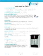
The WaterLogic WL100 provides clean and refreshing water with its advanced filtration system. To ensure proper installation, refer to the Installation Procedures Manual available for free download on 88.208.23.73:8080. This manual will guide you through the setup process, ensuring optimal performance of your WaterLogic WL100.
Share
Download


Reviews:
No comments
Related manuals for WL100

NBX 100
Brand: 3Com Pages: 57

MagnaLatch ALERT
Brand: D&D Technologies Pages: 2

Omni Pro II
Brand: HAI Pages: 2

Studio
Brand: Vectaire Pages: 2

VM Series
Brand: Davey Pages: 28

Arc 140
Brand: Jasic Pages: 18

ACUSTICA H series
Brand: RCF Pages: 10

PROFESSIONAL 5965-01
Brand: Simer Pages: 19

PA102
Brand: Renkforce Pages: 4

Area Line Pressure Alarm
Brand: BeaconMedaes Pages: 10

Soundbar 80
Brand: NEC Pages: 16

Diago
Brand: BWT Pages: 12

SAPPHIRE COMPACT 309150001
Brand: Hygood Pages: 6

BW RAS 120
Brand: Black Widow Security Pages: 6

O 5.4
Brand: Becker Pages: 5

6-120
Brand: John Wood Pages: 28

GQ450
Brand: Karaoke USA Pages: 20

SMART 60
Brand: Schenker Pages: 44


