background image

10/4/2010 


Installation Guide 

Applies to Waterous 

“Skid” Model 


150-70  

200-100 

Rev 1 


FOR INSTALLATION CENTER USAGE ONLY 


Unit Serial Number

 ______________________ 


Waterous, Arizona Operations 

7612 North 74th Ave. 

Glendale, Arizona 85303 

623-979-3398 

Fax: 623-979-6949 

www.waterousco.com 


Summary of Contents for 150-70

Page 1: ...o Waterous Skid Model 150 70 200 100 Rev 1 FOR INSTALLATION CENTER USAGE ONLY Unit Serial Number ______________________ Waterous Arizona Operations 7612 North 74th Ave Glendale Arizona 85303 623 979 3398 Fax 623 979 6949 www waterousco com ...

Page 2: ...rt s component s or product s Waterous will not be responsible for any replacement part s component s or product s that are not furnished or purchased from Waterous WARRANTY INSERT last page The aforesaid warranty excludes any responsibility or liability of WATEROUS for c any product or part altered modified serviced or repaired other than by WATEROUS without its prior written consent and d the co...

Page 3: ...p 11 I Initial Compressor System Power up 12 SECTION 4 VERIFYING THE AUTO SYNC AIR BALANCING SYSTEM 13 A UNLOAD mode verification 13 B FIXED mode verification 14 C AUTO mode verification 14 SECTION 5 OPTIONAL PROGRAMMABLE VALVE CONTROLLER 15 A Operation 15 B Programming 15 C Wiring Harness Pin Out 15 SECTION 6 SUGGESTED THIRD PARTY COMPONENTS 16 A Suggested components for CAFS discharges 16 B Sugg...

Page 4: ... Positive right 7 Figure 8 Typical CAFS Discharge 16 Figure 2 Electrical Auto sync section 28 Figure 3 Basic Front Panel 31 Figure 4 Basic CAFS Layout 32 Figure 5 Hydraulic Schematic 5in Vertical Sump 33 Figure 6 Electrical Schematic Auto sync 34 Figure 7 Air Schematic Electric Auto sync 90 Inlet 35 Figure 8 Tank Placement Low 36 Figure 9 Tank Placement High 37 ...

Page 5: ...gine unless the system is connected to a source of water The pump and compressor are operating whenever the engine is running Running without water will seriously damage the pump and the compressor Note The instructions are for a typical system A custom order system will have a similar installation procedure The illustrations shown in this manual may differ slightly from the parts that were shippe...

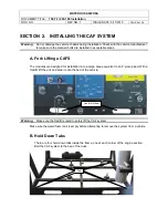
Page 6: ...AFS The modules are designed for installation into a cargo area equivalent to an 8 pickup bed With a forklift lift the unit and slide it onto the bed of the vehicle Warning Make sure the forklift is rated to safely lift the CAF system Make sure the water foam tank is empty before attempting to remove the system from a vehicle B Hold Down Tabs There are four hold down tabs inside the frame one at e...

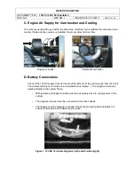
Page 7: ... D Battery Connections Connect the 12VDC supply to the terminals at the left side of the unit as seen from the front The positive terminal is mounted on an insulated block Figure 1 The negative terminal is welded directly to the system frame Both positive and negative cables must be adequately sized to supply power to the system The negative terminal must be connected to the truck chassis The chas...

Page 8: ...inc or made of any metal high in zinc because some fuels will react with the tank and build up a soapy zinc compound that clogs the fuel injectors Tanks must be constructed to have a large surface area at any fuel level to facilitate out gassing Tanks must have a sludge drain valve at the bottom III Supply and Return Fuel Lines for Fuel Injection Fuel injected engines require a closed loop full of...

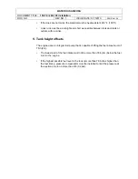
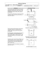
Page 9: ...inlets or outlets with no kinks V Tank height offsets The engine uses an integral fuel pump that is capable of lifting the fuel a maximum of 78in 2m The lowest part of the fuel intake must not be more than 78in 2m below the fuel inlet on the engine If the highest possible fuel level in the tank is more than 79 inches higher than the fuel inlet a pressure compensator must be installed to limit the ...

Page 10: ...e can use almost all of the fuel from the tank The best practice is for the supply line opening to be 1 5 inches from the bottom of the tank to avoid drawing sludge or water into the line with the return line ending 0 5 inch below the supply line opening Recommended for separate auxiliary tank NOT Recommended for shared tanks Ending the return line at the top of the tank is not recommended for sha...

Page 11: ... add more oil later to compensate for oil that remains in the hydraulic lines and the compressor Oil used in the hydraulic system is ISO 68wt hydraulic oil It must be Low foaming or Anti foam 7 Make sure the foam proportioner if installed is operating properly see the manufacturer s installation guide B Initial Engine and Fire Pump Power up Before powering up the compressor make sure the engine an...

Page 12: ...f the compressor to pre oil it 2 Replace the air filter plumbing 3 Place the Auto Sync system in UNLOAD 4 Start the engine and engage the PTO 5 With the system powered up turn the Auto Sync to the FIXED positions Air pressure should rise to about 150 PSI 10 3 bar 6 Check for leaks by listening for hissing noises at the fittings 7 Shut the engine off allow the pressure to bleed off and then add oil...

Page 13: ...e factory before shipment In most cases the factory settings will be satisfactory for typical CAFS and auxiliary air applications If the system fails any verification step go to Adjusting the Auto Sync Air Balancing System and follow the steps in the order given A UNLOAD mode verification 1 Set the controls on the Auto Sync control panel to UNLOAD center position Electric Auto Sync Controls 2 Comp...

Page 14: ...abilizes 2 The air pressure should be between 145 150 PSI 9 9 10 3 bar and stable C AUTO mode verification 1 The fire pump must have 100 PSI 6 9 bar at the main discharge with minimal flow 2 Place the Auto Sync controls to AUTO switch lights green 3 Read the main air pressure and water discharge pressure gauges 4 The pressure readings should be the same air may be up to 5 higher 5 Verify the Auto ...

Page 15: ...osition of each set point as well The INCREASE DECREASE switch allows the user to adjust valve position by one percentage point at a time towards open or close The OPEN CLOSE switch gives one touch access to each of the set points B Programming Each of the three programmable set points corresponds to a value within the 0 to 100 range The value for each set point is easily adjusted by using both to...

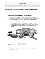
Page 16: ...charge system is not covered in this guideline please contact Waterous Note Waterous strongly suggests that every CAFS discharge have an air check valve and a water check valve as shown below The air check valve prevents foam solution from back flowing into the compressor and contaminating the oil The water check valve isolates the discharge preventing CAF from back flowing into the foam solution ...

Page 17: ... 2 Use 3 4 ID air hose Auxiliary Air Outlet Use 3 8 ID air hose II Air Brake Air brake tubing may also be used provided strict attention is paid to the inside diameters Size Working PSI Burst PSI 375 OD is 250 ID 150 1400 500 OD is 375 ID 150 950 625 OD is 500 ID 150 900 750 OD is 625 ID 150 800 Discharge fittings and Kits Lists are available on request for various discharges III Hydraulic For the...

Page 18: ...the correct level and that the batteries are charged and connected If the problem persists see the user manual s troubleshooting section Compressor System Before you start make sure of the following The oil level in the sump is correct The water supply to the oil cooler is adequate The oil cooler s strainer is clean The air lines do not have leaks The hydraulic lines do not have leaks ...

Page 19: ...the air solenoid and check operation of solenoid Air discharge solenoid not working Repair replace solenoid Air solenoid working leak between solenoid and discharge Repair leak Air check valve defective Replace or correct installation Trim valve out of adjustment Refer to trim valve instructions Restricted minimum pressure valve Clean rust or debris from valve Air plumbed before discharge valve se...

Page 20: ...f of the sight glass on level surface Excess of 200 CFM air flow on 200 CFM systems Back down RPM s and flow CAFS to relieve pressure then recheck Replace Air Oil Separator Filter Air oil Separator Filter torn or damaged could be caused by air flow of higher than 200CFM System being operated at higher than capacity Excessive compressor bleed down time on shutoff Systems vary in bleed down time If ...

Page 21: ...rtioning control OFF or turned too low foam tank empty Make sure proportioner is turned on foam supply valve is open foam tank has concentrate Y strainer is clean and supply line is connected to injector Discharge hose shaking slug flow Foam proportioner ON setting correct and tank has foam concentrate but not providing foam solution Refer to foam proportioner manufacturer s instructions for detai...

Page 22: ...in lower RPM Not allowing compressor to bleed down before engaging clutch again Allow for bleed down Contaminated clutch disc Clean or replace Safety pop off valve opening at low pressure Auto Sync system out of balance Adjust the Auto Sync system making sure to not open the trim valve on the compressor more than 3 turns Sump fire damaged pop off valve Check system for other damage and replace val...

Page 23: ...one discharge valve and run in water until pump is completely filled and all air is expelled 4 Close discharge valve apply pressure to system and watch for leaks or overflowing water tank A pressure of 100 psi is sufficient DO NOT EXCEED RECOMMENDED PRESSURE 1 If pump has not been operated for several weeks packing may be dried out 2 Close discharge and drain valves and cap intake openings 3 Opera...

Page 24: ...sed enough for priming pumping large volumes of water may produce whirlpools which will allow air to be drawn into intake hose Whenever possible place end of Intake hose at least two feet below water source High point In Intake line If possible avoid placing any part of Intake hose higher than pump inlet If high point cannot be prevented close discharge valve as soon as pressure drops and prime ag...

Page 25: ...sfer valve to move completely into new position will seriously impair pump efficiency Pump Impeller s or wear rings badly worn Install undersize wear rings if Impeller to wear ring clearance is within limits indicated in MAINTENANCE INSTRUCTIONS If not install new impeller s and wear rings Intake strainer Intake screens or impeller vanes fouled with debris Remove intake strainer and hose and clear...

Page 26: ...ed when discharge valves are closed Sticky pilot valve Disassemble and clean Replace noticeably worn parts Plugged tube lines Disconnect lines and Inspect Relief Valve Malfunction B Pressure will not return to original setting after discharge valves are reopened Sticky pilot valve Disassemble and clean Replace noticeably worn parts Sticky main valve Disassemble and clean Replace noticeably worn pa...

Page 27: ...lance valve in an attempt to improve performance If unauthorized adjustments to the Auto Sync are a problem we suggest placing a seal over the adjustment points This will let maintenance personnel know if the system has been tampered with A Electric Auto Sync Initial Setup Colored hoses and fittings are supplied with the compressor kit for the average installation The schematic is color coded to s...

Page 28: ...l Auto sync section 2 Close all air discharges 3 Locate the Air Inlet Trim Valve AITV near the air inlet on the compressor 4 Turn the AITV valve clockwise until it is completely closed then open it three full turns 5 Locate the Piloted Balance Valve PBTV and turn the needle valve counterclockwise to full open Air Inlet Trim valve ...

Page 29: ...ng pressure is 145 150 PSI 9 9 10 3 bar Monitor the air pressure reading as you adjust the regulator screw Give the system several seconds to stabilize between adjustments and make partial turns of the screw to avoid overshooting the target pressure Turning the screw IN CW will increase pressure Turning the screw OUT CCW will decrease pressure 4 After the desired fixed pressure is achieved tighten...

Page 30: ...ssure is too low turn the AITV counterclockwise 1 2 turn to open it and check pressures If the air pressure is still too low open the valve another 1 2 turn and check the pressures again Do not open the Air Inlet Trim Valve more than this Use the PBTV if the pressure remains too low 6 If the air pressure remains too low close the needle valve on the Piloted Balance Trim Valve PBTV one full turn cl...

Page 31: ...WATEROUS ARIZONA DOCUMENT TITLE 150 70 200 100 Installation DOC NO REV NO 1 ISSUE DATE 6 17 2010 PAGE 31 of 38 Figure 4 Basic Front Panel ...

Page 32: ...WATEROUS ARIZONA DOCUMENT TITLE 150 70 200 100 Installation DOC NO REV NO 1 ISSUE DATE 6 17 2010 PAGE 32 of 38 Figure 5 Basic CAFS Layout ...

Page 33: ...WATEROUS ARIZONA DOCUMENT TITLE 150 70 200 100 Installation DOC NO REV NO 1 ISSUE DATE 6 17 2010 PAGE 33 of 38 Figure 6 Hydraulic Schematic 5in Vertical Sump ...

Page 34: ...WATEROUS ARIZONA DOCUMENT TITLE 150 70 200 100 Installation DOC NO REV NO 1 ISSUE DATE 6 17 2010 PAGE 34 of 38 Figure 7 Electrical Schematic Auto sync ...

Page 35: ...WATEROUS ARIZONA DOCUMENT TITLE 150 70 200 100 Installation DOC NO REV NO 1 ISSUE DATE 6 17 2010 PAGE 35 of 38 Figure 8 Air Schematic Electric Auto sync 90 Inlet ...

Page 36: ...WATEROUS ARIZONA DOCUMENT TITLE 150 70 200 100 Installation DOC NO REV NO 1 ISSUE DATE 6 17 2010 PAGE 36 of 38 Figure 9 Tank Placement Low ...

Page 37: ...WATEROUS ARIZONA DOCUMENT TITLE 150 70 200 100 Installation DOC NO REV NO 1 ISSUE DATE 6 17 2010 PAGE 37 of 38 Figure 10 Tank Placement High ...

Page 38: ...by the manufacturer thereof which if assignable WATEROUS will assign to Buyer if requested by Buyer c any product or part altered modified serviced or repaired other than by WATEROUS without its prior written consent and d the cost of dismantling removing transporting storing or insuring the defective product or part and the cost of reinstallation e normal wear items including but not limited to b...

Reviews: