


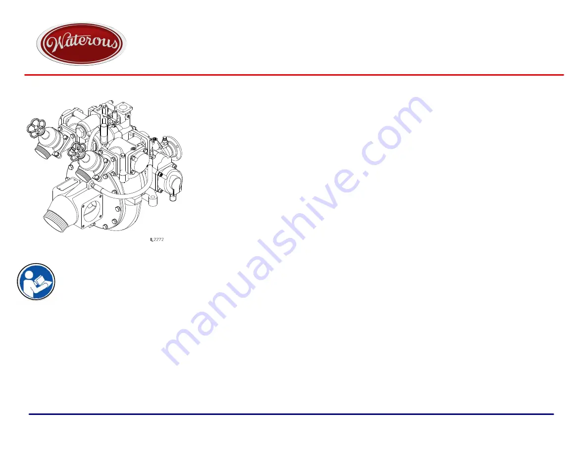
Read through the safety information
and overhaul instructions carefully
before repairing your Waterous HL
Series Fire Pump.
Table of Contents
Introduction
2
. . . . . . . . . . . . . . . . . . . . . . . . . . . . . . . . . . . . . . . . . . . . . . . . . . .
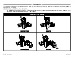
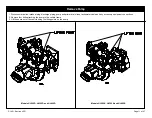
Pump Models
2
. . . . . . . . . . . . . . . . . . . . . . . . . . . . . . . . . . . . . . . . . . . . . . . . . .
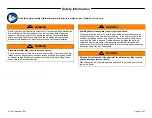
Safety Information
3
. . . . . . . . . . . . . . . . . . . . . . . . . . . . . . . . . . . . . . . . . . . . . .
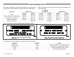
Ordering Repair Parts
4
. . . . . . . . . . . . . . . . . . . . . . . . . . . . . . . . . . . . . . . . . .
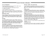
General Overhaul Information
5
. . . . . . . . . . . . . . . . . . . . . . . . . . . . . . . . . . .
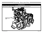
Pump Components
6
. . . . . . . . . . . . . . . . . . . . . . . . . . . . . . . . . . . . . . . . . . . . .
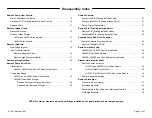
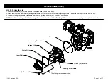
Disassembly Index
7
. . . . . . . . . . . . . . . . . . . . . . . . . . . . . . . . . . . . . . . . . . . . .
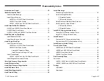
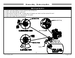
Reassembly Index
8
. . . . . . . . . . . . . . . . . . . . . . . . . . . . . . . . . . . . . . . . . . . . . .
K Series Transmission Overhaul
See F-1031, Section 4309
. . . . . . . . .
NOTE: Instructions subject to change without notice
Waterous Company, 125 Hardman Avenue South, South St. Paul, Minnesota 55075 USA (651) 450-5000
www.waterousco.com
F-1031, Section 4321 (Rev:
6/7/19
)
HL Series Centrifugal Fire Pumps
Overhaul Instructions


