All content in this instruction is property of the Waterous Company. Instructions subject to change without notice.
All content in this instruction is property of the Waterous Company. Instructions subject to change without notice.
All content in this instruction is property of the Waterous Company. Instructions subject to change without notice.
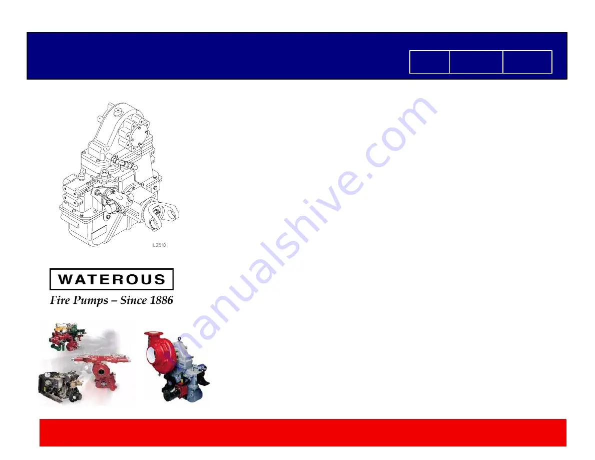
TC10 Power Take-of f Overhaul Instructions
TC10 Power Take-of f Overhaul Instructions
Overhaul Instructions
Form No.
T-360
Issue Date
Rev. Date
01/19/06
1/9/18
TC10 Power Take-Off
Waterous Company 125 Hardman Avenue South, South St. Paul, Minnesota 55075 USA (651) 450-5000
Instructions subject to change without notice.
Table of Contents
Introduction
1
. . . . . . . . . . . . . . . . . . . . . . . . . . . . . . . . . . . . . . . . . . . . . . . . . . . . .
General Description
1
. . . . . . . . . . . . . . . . . . . . . . . . . . . . . . . . . . . . . . . . . . . .
Disassembly
1
. . . . . . . . . . . . . . . . . . . . . . . . . . . . . . . . . . . . . . . . . . . . . . . . . . .
Propeller Shaft Disconnect and Accessory Removal
1
. . . . . . . . . . . . . . . . .
Eclipse ES CAFSystem Removal from PTO
1
. . . . . . . . . . . . . . . . . . . . . . . . .
Pump Removal from Transmission
2
. . . . . . . . . . . . . . . . . . . . . . . . . . . . . . . . .
Disassembly of PTO
3
. . . . . . . . . . . . . . . . . . . . . . . . . . . . . . . . . . . . . . . . . . . .
Removal End Yokes
3
. . . . . . . . . . . . . . . . . . . . . . . . . . . . . . . . . . . . . . . . . . . . .
Coupling Shaft Housing Removal
4
. . . . . . . . . . . . . . . . . . . . . . . . . . . . . . . . . .
Removing the Bottom Section
4
. . . . . . . . . . . . . . . . . . . . . . . . . . . . . . . . . . . . .
Removal of the Chain
5
. . . . . . . . . . . . . . . . . . . . . . . . . . . . . . . . . . . . . . . . . . . .
Removal of the Drive Shaft and Housing
5
. . . . . . . . . . . . . . . . . . . . . . . . . . . .
Removal of Shift Components (Pneumatic, Electric Shift)
6
. . . . . . . . . . . . .
Removal of Mid-Section from Cap
7
. . . . . . . . . . . . . . . . . . . . . . . . . . . . . . . . .
Disassembly of Driven Shaft Assembly
7
. . . . . . . . . . . . . . . . . . . . . . . . . . . . .
Front Facing End Yoke
7
. . . . . . . . . . . . . . . . . . . . . . . . . . . . . . . . . . . . . . . .
Rear Facing End Yoke
8
. . . . . . . . . . . . . . . . . . . . . . . . . . . . . . . . . . . . . . . .
Front Facing Hydraulic Pump Provision
8
. . . . . . . . . . . . . . . . . . . . . . . . .
Rear Facing Hydraulic Pump Provision
9
. . . . . . . . . . . . . . . . . . . . . . . . . .
Front Facing End Yoke/Rear Facing Hydr. Pump Prov.
9
. . . . . . . . . . . .
Rear Facing End Yoke/Front Facing Hydr. Pump Prov.
10
. . . . . . . . . . .
Eclipse Mounted CAFS
10
. . . . . . . . . . . . . . . . . . . . . . . . . . . . . . . . . . . . . .
Disassembly of Coupling Shaft Assembly
11
. . . . . . . . . . . . . . . . . . . . . . . . . .
Disassembly of Drive Shaft Assembly
11
. . . . . . . . . . . . . . . . . . . . . . . . . . . . .
Inspection and Repair
12
. . . . . . . . . . . . . . . . . . . . . . . . . . . . . . . . . . . . . . . . . . .
Reassembly
13
. . . . . . . . . . . . . . . . . . . . . . . . . . . . . . . . . . . . . . . . . . . . . . . . . .
Installing Bearings, Oil Seals and Gaskets
13
. . . . . . . . . . . . . . . . . . . . . . . . .
Reassembly of the Driven Shaft
13
. . . . . . . . . . . . . . . . . . . . . . . . . . . . . . . . . .
Front Facing End Yoke
13
. . . . . . . . . . . . . . . . . . . . . . . . . . . . . . . . . . . . . . .
Rear Facing End Yoke
14
. . . . . . . . . . . . . . . . . . . . . . . . . . . . . . . . . . . . . . .
Front Facing Hydraulic Pump Provision
15
. . . . . . . . . . . . . . . . . . . . . . . .
Rear Facing Hydraulic Pump Provision
16
. . . . . . . . . . . . . . . . . . . . . . . . .
Front Facing End Yoke/Rear Facing Hydr. Pump Prov.
17
. . . . . . . . . . .
Rear Facing End Yoke/Front Facing Hydr. Pump Prov.
18
. . . . . . . . . . .
Eclipse Mounted CAFS
19
. . . . . . . . . . . . . . . . . . . . . . . . . . . . . . . . . . . . . .
Dowel Pins and Spacer Installation
20
. . . . . . . . . . . . . . . . . . . . . . . . . . . . . . .
Reassembly of the Shift Assembly (Pneumatic or Electric)
21
. . . . . . . . . . .
Reassembly of the Cap and Mid-Section
23
. . . . . . . . . . . . . . . . . . . . . . . . . .
Reassembly of the Drive Shaft and Drive Shaft Housing
24
. . . . . . . . . . . . .
Installing the Chain
26
. . . . . . . . . . . . . . . . . . . . . . . . . . . . . . . . . . . . . . . . . . . . .
Reassembly of the Bottom Section
28
. . . . . . . . . . . . . . . . . . . . . . . . . . . . . . .
Shift Position Adjustments
29, 30
. . . . . . . . . . . . . . . . . . . . . . . . . . . . . . . . . . . .
Coupling Shaft and Housing Assembly
31
. . . . . . . . . . . . . . . . . . . . . . . . . . . .
Coupling Shaft Housing to Case Assembly
32
. . . . . . . . . . . . . . . . . . . . . . . . .
Reassembly of Miscellaneous Items and Accessories
33
. . . . . . . . . . . . . . .
Eclipse ES CAFSystem Installation onto PTO
34
. . . . . . . . . . . . . . . . . . . . . .
Propeller Shaft Connection and Accessory Installation
35
. . . . . . . . . . . . . . .
Lubrication and Final Checks
35
. . . . . . . . . . . . . . . . . . . . . . . . . . . . . . . . . .
Illustrations
1.
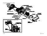
Eclipse ES CAFSystem Removal
2
. . . . . . . . . . . . . . . . . . . . . . . . . . . . . . . . .
2.
Eclipse ES CAFSystem Air Clutch Assembly (Side View)
2
. . . . . . . . . . . . .
3.
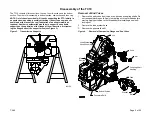
PTO Support
3
. . . . . . . . . . . . . . . . . . . . . . . . . . . . . . . . . . . . . . . . . . . . . . . . . . .
4.
Removal of End Yokes
3
. . . . . . . . . . . . . . . . . . . . . . . . . . . . . . . . . . . . . . . . . .
5.
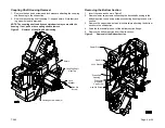
Removal of Coupling Shaft Housing
4
. . . . . . . . . . . . . . . . . . . . . . . . . . . . . . .
6.
Removal of the Bottom Section
4
. . . . . . . . . . . . . . . . . . . . . . . . . . . . . . . . . . .
7.
Removable Connecting Pin Set
5
. . . . . . . . . . . . . . . . . . . . . . . . . . . . . . . . . . .
8.
Chain Removal
5
. . . . . . . . . . . . . . . . . . . . . . . . . . . . . . . . . . . . . . . . . . . . . . . . .
9.
Removal of Drive Shaft and Housing
5
. . . . . . . . . . . . . . . . . . . . . . . . . . . . . .
10.
Removal of Shift Components
6
. . . . . . . . . . . . . . . . . . . . . . . . . . . . . . . . . . . .
11.
Removal of Mid-Section from Cap
7
. . . . . . . . . . . . . . . . . . . . . . . . . . . . . . . .
12.
Disassembly of Driven Shaft Assemblies (Figures 12-18)
7
. . . . . . . . . . . .
19.
Coupling Shaft Disassembly
11
. . . . . . . . . . . . . . . . . . . . . . . . . . . . . . . . . . . . .
20.
Drive Shaft Disassembly -
Shift Collar and Oil Seal Removal
11
. . . . . . . . . . . . . . . . . . . . . . . . . . . . . . . .
21.
Drive Shaft Disassembly
12
. . . . . . . . . . . . . . . . . . . . . . . . . . . . . . . . . . . . . . . .
22.
Needle Bearing Removal from Sprocket
12
. . . . . . . . . . . . . . . . . . . . . . . . . . .
23.
Reassembly of the Driven Shaft (Figures 23-29)
13
. . . . . . . . . . . . . . . . . . .
30.
Dowel Pins and Spacer Installation for Extended Drop Cases
20
. . . . . . . .
31.
Pivot Pin, Shaft Bushing and Sleeve Bearing Installation
21
. . . . . . . . . . . .
32.
Shift Arm Assembly
21
. . . . . . . . . . . . . . . . . . . . . . . . . . . . . . . . . . . . . . . . . . . .
33.
Shift Assembly (Pneumatic or Electric)
22
. . . . . . . . . . . . . . . . . . . . . . . . . . . .
34.
Mid-Section Assembly
23
. . . . . . . . . . . . . . . . . . . . . . . . . . . . . . . . . . . . . . . . .
35.
Cap and Mid-Section Assembly
23
. . . . . . . . . . . . . . . . . . . . . . . . . . . . . . . . .
36.
Needle Bearing Installation into Drive Sprocket
24
. . . . . . . . . . . . . . . . . . . .
37.
Drive Shaft Installation into Drive Sprocket
24
. . . . . . . . . . . . . . . . . . . . . . . .
38.
Drive Assembly into Drive Housing
25
. . . . . . . . . . . . . . . . . . . . . . . . . . . . . . .
39.
Drive Shaft/Housing Assembly Installation
25
. . . . . . . . . . . . . . . . . . . . . . . . .
40.
Optional Electronic Tachometer
26
. . . . . . . . . . . . . . . . . . . . . . . . . . . . . . . . . .
41.
Installing the Chain
26
. . . . . . . . . . . . . . . . . . . . . . . . . . . . . . . . . . . . . . . . . . . . .
42.
Connecting Pin Set
27
. . . . . . . . . . . . . . . . . . . . . . . . . . . . . . . . . . . . . . . . . . . . .
43.
Connecting Pin Orientation
27
. . . . . . . . . . . . . . . . . . . . . . . . . . . . . . . . . . . . . .
44.
Assembling Items on the Bottom Section
28
. . . . . . . . . . . . . . . . . . . . . . . . . .
45.
Assembling Bottom Section to the Cap and Mid-Section
28
. . . . . . . . . . . .
46.
Retainer Installation
29
. . . . . . . . . . . . . . . . . . . . . . . . . . . . . . . . . . . . . . . . . . . .
47.
Locking Arm Rotation Restrictions
30
. . . . . . . . . . . . . . . . . . . . . . . . . . . . . . . .
48.
Coupling Shaft Assembly
31
. . . . . . . . . . . . . . . . . . . . . . . . . . . . . . . . . . . . . . .
49.
Coupling Shaft Housing Assembly
31
. . . . . . . . . . . . . . . . . . . . . . . . . . . . . . .
50.
Assembling Coupling Shaft Housing to Case
32
. . . . . . . . . . . . . . . . . . . . . .
51.
End Yoke Assembly
33
. . . . . . . . . . . . . . . . . . . . . . . . . . . . . . . . . . . . . . . . . . . .
52.
Shift Assembly
33
. . . . . . . . . . . . . . . . . . . . . . . . . . . . . . . . . . . . . . . . . . . . . . . .


