background image

SMEC 300 Soil


Moisture Sensor


PRODUCT MANUAL


Item # 6470

-

6, 6470

-

20


Summary of Contents for SMEC 300 Soil

Page 1: ...SMEC 300 Soil Moisture Sensor PRODUCT MANUAL Item 6470 6 6470 20 ...

Page 2: ... This manual will familiarize you with the features and operation of your new WaterScout SMEC 300 Soil Moisture Sensor Please read this manual thoroughly before using your instrument For customer support or to place an order call Spectrum Technologies Inc at 800 248 8873 or 815 436 4440 between 7 30 am and 5 30 p m CST FAX at 815 436 4460 or E Mail at info specmeters com www specmeters com Spectru...

Page 3: ...e detected by the sensor circuitry and cor related to the soil s moisture content The salinity of the soil solution irrigation water or fertilizer solution is an important parameter affecting the root zone envi ronment Any of these factors can have a significant effect on plant growth and physiology The easiest way to monitor salin ity is by measuring the electrical conductivity EC EC is strongly ...

Page 4: ...ch receives the least amount of water from the irrigation system will tell you when that area becomes critically dry and is in need of attention Sites that have the greatest fluctuation in soil moisture will exhibit the greatest level of EC variability as well A sin gle sensor should be placed in the middle of the root zone Unless they are installed in separate containers SMEC 300 sensors connecte...

Page 5: ...efore good contact between the soil and sen sor is important Stones and air pockets next to the sensor will affect the accuracy of the readings Because it is sen sitive to differences in dielectric permittivity care should be taken not to install the sensor in or near metal ...

Page 6: ...tlines the compatibility of the sensor with the various WatchDog weather products WatchDog Pups and Pup Stations No restrictions Station Station Type Station FW version Number of Sensors Compatible Channels Potentially unavailable channels 1225 1250 Micro N A 0 Incompatible 1400 1525 1650 Micro 2 0 2 A D 1200 1425 1450 Micro 2 0 1 D 2475 Mini 3 8 1 A 2450 Mini 3 8 2 A B 2425 Mini 3 8 3 A B C 2400 ...

Page 7: ... the sensor from one conductive pad to an other When other SMEC 300 sensors are in close prox imity to each other and within the same body of soil a small amount of current can leak to the grounded pad on another sensor resulting in a slightly lower EC reading To minimize or eliminate the impact of SMEC 300 sen sors interfering with each other 1 Connect each sensor to a separate Spectrum logger pr...

Page 8: ...mportant points to remember when calibrating the EC sensor 1 Be careful not to touch the carbon ink electrodes Oils from your fingers can affect the accuracy of the sensor Before calibrating the electrodes should be cleaned well with alcohol 2 Immerse the sensor up to the immer sion indicator on the sensor molding indicated by arrow in image to right 3 Wait until the sensor has come to thermal equ...

Page 9: ... be taken in the following media Air In air the sensor should read a VWC of 0 Water In distilled water the sensor should read a VWC of about 55 in Standard mode and about 68 in Soilless mode Saturated Playground Sand Add water to playground sand until the surface glistens and no additional water can permeate the sand The sen sor should read a VWC of about 29 in Standard mode and about 60 in Soille...

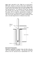
Page 10: ...r with a hammer or other blunt instrument as this could damage the sensor electronics If the soil is very hard a small slit can be dug into the soil with a knife or shovel to facilitate easier insertion Subsequently pushing that same implement into the ground surrounding the sen sor will improve the contact between soil and sensor Deep Installation Vertical Orientation To install the sensor in a v...

Page 11: ... that it is possible to determine that the sensor will be completely surrounded by tamped soil and that the sensor is being installed to the desired depth The access hole should then be carefully backfilled with native soil and tamped down to eliminate air pockets Horizontal Orientation Digging a small hole or trench in the soil allows the sen sors to be installed horizontally The sensors are push...

Page 12: ...ng Suggestions for protecting sensor cables from rodents For vertical installations run sensor cables through PVC pipe This can be the same tube used as an installation tool For sensor cable that will be running parallel to the ground either above or below the soil surface the sensor cable can be fed through flexible conduit or drip irrigation tubing When using drip irrigation tubing it is prefera...

Page 13: ...o com plete The procedure is briefly outlined below Readings of the soil moisture circuit can be taken either with the Soil Sensor Reader or a WatchDog weather station In either case the device should be set to Raw AD mode For the weather stations when channel A is configured to read Raw Sensor raw it will read the soil moisture cir cuit only Nothing will be read on channels B or C 1 Build a small...

Page 14: ...the container to completely saturate Take a sensor reading 7 Transfer the container to the scale and measure the mass It is advisable to have a tray to hold the container to keep water from spilling on the bench Be sure to zero out the tare weight of the tray At this point the procedure is to simply allow the contain er to dry while periodically taking simultaneous weight and sensor readings Initi...

Page 15: ... and the calculated VWC values Regression analysis can then be performed on raw sensor data and the calcu lated VWC values to develop an equation to convert from measured readings to actual VWC A calibration curve can also be obtained by gradually wet ting a pre measured amount of soil with known incre ments of water Care must be taken to return the soil to its original bulk density before a senso...

Page 16: ...nd shaking or tumbling it into the soilless media This is best done on a mass wetness MW basis where mass wetness is defined as 2 Where MW target mass wetness expressed as percent Mwater mass of water needed Mmaterial total air dry mass of sample We have found that for sphagnum peat moss the relation ship between volumetric water content VWC and MW is on the order of This can be used as a benchmar...

Page 17: ...t 6 samples of soilless media Each sample should be slightly more than is required to fill 3 containers 4 Weigh the material and place it into a plastic bag Es tablish 6 different water content conditions by mixing wa ter into the air dry material Add enough water to bring the material to the desired MW The needed amount of water can be determined by rearranging equation 2 3 5 Twist or seal the ba...

Page 18: ...etely air dry the materi al in each container DO NOT MIX the material from each container Find the air dry weight for the material in each container 10 The volumetric water content for each container is cal culated as follows Where VWC Volumetric water content Mwet total Total mass of container and wet material Mdry only Mass of air dry material Mcont Mass of container ρw Density of water 1g ml Vc...

Page 19: ...ecause as water content decreases the conductive path becomes increasingly tortuous thus decreasing the EC even though the concentration of salt in the remaining liquid is increasing Such an EC measurement is some times referred to as bulk EC because it reflects how well electrons in the bulk soil are conducted The SMEC 300 measures bulk EC An alternative measure of EC is pore EC This is the value...

Page 20: ...city is defined as the condition that exists after a saturated soil is allowed to drain to the point where the pull of gravity is no longer sufficient to remove any additional water Water draining from a soil profile can not in general be taken up by plant roots On the oppo site end of the spectrum permanent wilting point is the highest moisture level at which an indicator plant cannot recover tur...

Page 21: ...21 Figure 1 ...

Page 22: ...C 0 to 10 mS cm Temp 60 to 185 F 50 to 85 C Resolution VWC 0 1 EC 0 01 mS cm Temp 0 1o F 0 1 C Power 3V 6 to 10mA Output Analog voltage time division multiplexed Oscillator Frequency 80 MHz Accuracy VWC 3 EC 2 Temp 1o F 0 6 C T 25 F 30 C 1 5o F 0 6 C T 25 F 30 C Sensor Dimensions 2 8in 7cm x 1 2in 3cm Cable length 6 and 20ft extendable up to 50ft ...

Page 23: ...This warranty does not cover damage due to improper installation or use lightning negligence acci dent or unauthorized modifications or to incidental or consequential damages beyond the Spectrum prod uct Before returning a failed unit you must obtain a Re turned Materials Authorization RMA from Spec trum Spectrum is not responsible for any package that is returned without a valid RMA number or for...

Page 24: ...R 2 18 3600 Thayer Court Aurora IL 60504 800 248 8873 or 815 436 4440 Fax 815 436 4460 E Mail info specmeters com www specmeters com ...

Reviews: