SANTANNA AIR BLOWER INSTRUCTIONS
When installing and using this electrical equipment, basic safety precautions should always be followed, including
the following:
1. (For all units) Install to provide drainage of compartment for electrical components.
2. (For all units) WARNING - To reduce the risk of injury, do NOT permit children to use this product unless they are
closely supervised at all times.
3. (For permanently installed units only) A green colored wire (or a wire connector marked “G”, “GR”, “Ground”,
or “Grounding”) is provided with the switch box. To reduce the shock, connect this terminal or connector to
the grounding terminal of your electric service or supply panel with a continuous green insulated copper wire
equivalent in size to the circuit conductors supplying this equipment, but no small than No. 12AWG (3.3mm²).
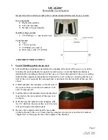
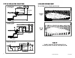
4. (For assemblies with air blowers) Install in accordance with Diagram 1 to keep spa or water out of electrical
equipment.
5. The unit must be installed within a suitable enclosure to restrict user access to the equipment or connections and
be of an enclosure type that will provide an ingress protection rating of IP24 or better.
BLOWER SIZING - AIR CHANNELS, AIR BARS, AIR CAPS, & AIR RINGS
Choosing the proper size of air blowers is critical for maximum performance and extended motor life. To determine
the correct blower size for a spa or hot tub, these element must be considered: 1. Water depth, 2. The number of air
holes.
WATER DEPTH
1. Total length of 2" pipe from blower to spa. For each 10 feet of 2" air line, add 1" to water depth.
2. Number of 90 degree angles used in the air line. For each 90 degree angle, add 1/2" to water depth.
3. Actual water depth (not total depth of spa).
For example: (refer to Diagram 1)
1. Air line is 30ft., all inclusive ....... add 3"
2. Five 90 degree turns .............. add 2 1/2"
3. Actual water depth ................. add 32"
Total ............................................... 37 1/2"
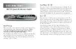
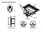
NUMBER OF AIR HOLES
The air holes in the spa floor and/or seat release the air perpetuated by the blower through the 2" air line. Table
2 below gives the most common air hole sizes and the corresponding number of air holes needed to release the
proper amount of air. An inadequate number of holes or holes that are too small create excessive heat buildup,
commonly called back up pressure, resulting in potential harm to the air blower.
If it is determined that the existing hole sizing
is incorrect, additional holes may be drilled or
the existing holes may be enlarged or more air
injectors added.
CAUTION: Be extra careful
not to drill through the bottom of the air
channel on your spa.
BLOWER SIZING - JETS
Originally designed for air channel aeration, the air blower also has been applied to boost spa jet turbulence
However, to be effective, care must be taken in installing (jets, jet orifice size, pump sizing, length of pipe run, etc.).
No common formula for sizing has been found 100% effective. Table 3 is a general guideline, assuming an average
pipe run of 15 to 25 feet total. The “bigger is better” idea will definitely not provide a trouble-free installation.
When sized with the proper circulation pump, the spa jet draws and mixes the
proper amount of air and water, thereby eliminating the need of additional
boost. Improper jet performance is seldom corrected with the air blower. The
Amperage Test (see other side) should always be applied in this situation to
assure no costly call-backs.
IMPORTANT NOTE
: To keep water from entering the blower, causing potential damage, a check valve (P/N 600-
8140) and a Hartford loop (refer to Diagram 1) must be used when plumbing blower to jets.
IMPORTANT SAFETY INSTRUCTIONS • SAVE THESE INSTRUCTIONS • PLEASE READ AND FOLLOW ALL INSTRUCTIONS
Part No.
HP
Volts
Amps
CFM
Up To
750-1011-280
1.0
110
6.5
115
35
750-1022-280
1.0
220
3.6
113
35
750-1511-280
1.5
110
7.6
120
750-1522-280
1.5
220
4.0
108
750-2011-280
2.0
110
9.0
128
750-2022-280
2.0
220
5.0
119
TABLE 1
Air Hole Size
Decimal Equivalent
No. of Air Holes
Total Orifice Diameter
1/8"
.0123
120
1.370
5/32"
.0192
73
1.336
3/16"
.0276
50
1.325
1/4"
.0491
30
1.369
No. of Jets
Blower Size
4-7
1 HP
8-13
1 1/2 HP
14 +
2 HP
TABLE 2
TABLE 3
810-0037.0618
©2018 Waterway Plastics
2200 East Sturgis Road, Oxnard CA 93030 • Phone 805.981.0262 • Fax 805.981.9403
www.waterwayplastics.com • waterway@waterwayplastics.com
Designed,
Engineered &
Manufactured
in the USA.