


INSTALLATION
Watkins Wellness
®
INSTALLATION REQUIREMENTS ................. 1
KIT INCLUDES
INSTALLATION REQUIREMENTS ................. 2
TOOLS REQUIRED
IMPORTANT INFORMATION
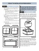
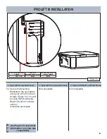
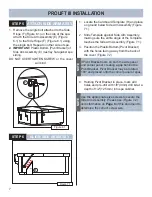
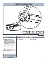
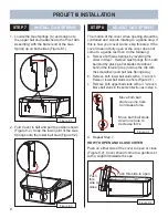
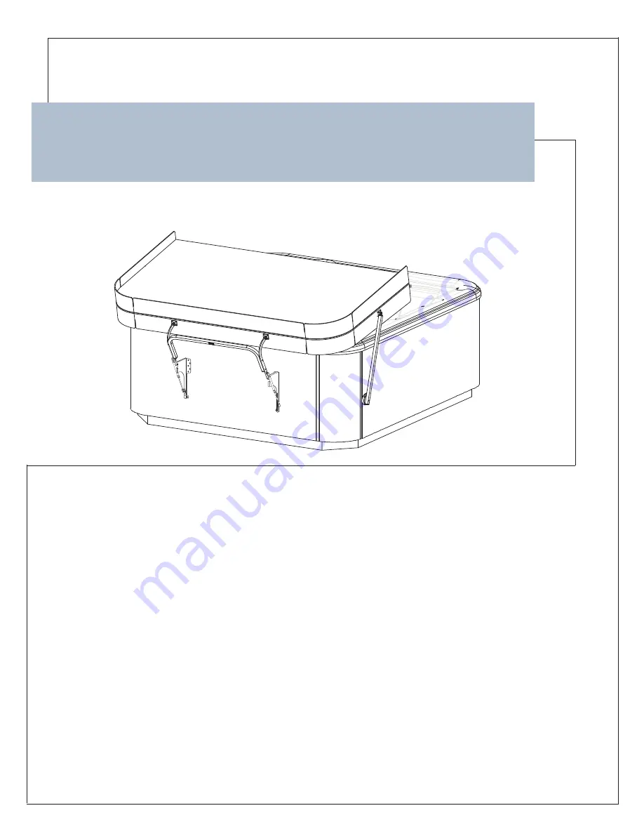
PROLIFT III INSTALLATION
PREPARATION ................................................. 3
INSTALL PREPARATION
LOCATE PLATES
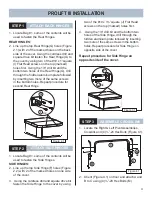
PROLIFT III INSTALLATION ............................ 4
ATTACH BACK HINGES
ATTACH SIDE HINGES
ASSEMBLE CROSSLINK
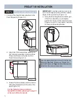
PROLIFT III INSTALLATION ............................ 5
ATTACH CROSSLINK ASSY.
PROLIFT III INSTALLATION ............................ 7
ATTACH SIDE ARM ASSY.
ALIGN SIDE ARM ASSY.
PROLIFT III INSTALLATION ............................ 9
INSTALL GAS SPRING
ADJUST GAS SPRING
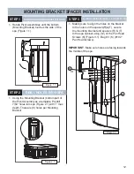
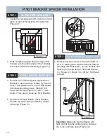
PROLIFT III INSTALLATION ...........................11
PROLIFT III SPACERS
TABLE OF CONTENTS
Of your
ProLift
®
III
INTENDED USE IN KIT # 74919
62701 E (04/19)
Summary of Contents for ProLift III
Page 15: ...14 Figure 6 2 PROLIFT III SPACERS BLANK...
Page 16: ...62701 E 04 19...