


Watkins Wellness
®
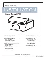
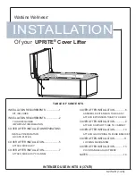
INSTALLATION
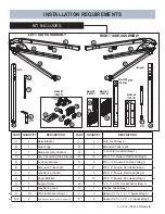
INSTALLATION REQUIREMENTS ......................1
KIT INCLUDES
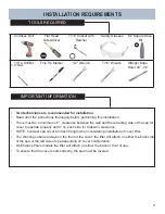
INSTALLATION REQUIREMENTS ......................2
TOOLS REQUIRED
IMPORTANT INFORMATION
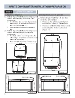
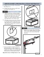
COVER LIFTER INSTALLATION REPARATION 3
INSTALL PREPARATION
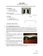
LOCATE PLATES
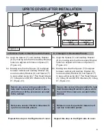
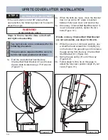
COVER LIFTER INSTALLATION ..........................5
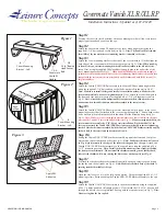
ATTACH SIDE ASSY.
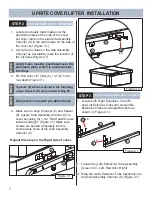
COVER LIFTER INSTALLATION ..........................7
ATTACH SIDE ASSY. CHANNEL
COVER LIFTER INSTALLATION ................. 8
ASSEMBLE EXTENSION TUBE ASSY.
ATTACH EXTENSION TUBE TO COVER
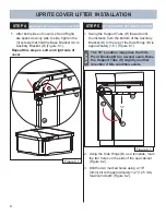
COVER LIFTER INSTALLATION ................. 9
ATTACH SUPPORT TUBE TO CABINET
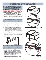
COVER LIFTER INSTALLATION ............... 10
ATTACH GAS SPRING TO BASE BRACKET
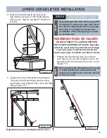
COVER LIFTER INSTALLATION ................11
LOCKING MECHANISM
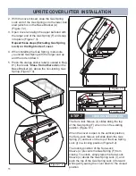
COVER LIFTER INSTALLATION ............... 13
COVER ANGLE ADJUSTMENT
NOTES ............................................................ 14
TABLE OF CONTENTS
Of your
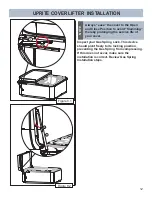
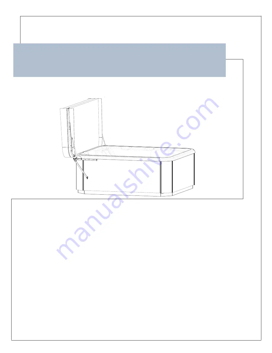
UPRITE
®
Cover Lifter
INTENDED USE IN KITS # (37876)
62732 D (1/20)
Summary of Contents for UPRITE
Page 15: ...14 NOTES ...
Page 16: ...62732 D 01 20 ...